Dataflow Domain
Using a dataflow domain, you can model and simulate a computationally intensive signal processing or multirate signal processing system. Dataflow domains simulate using a model of computation synchronous dataflow, which is data-driven and statically scheduled.
There are two primary reasons to use a dataflow domain in your model.
Improve simulation throughput with multithreaded execution.
A dataflow domain leverages the multicore CPU architecture of the host computer and can improve simulation speed significantly. The domain automatically partitions your model and simulates the system using multiple threads. By adding latency to your system, you can further increase concurrency and improve the simulation throughput of your model.
Automatically infer signal sizes for frame-based multirate models.
When the Automatic frame-size calculation parameter is enabled, dataflow domains automatically calculate frame sizes and insert buffers into your model, avoiding signal size propagation errors in multirate signal processing systems.
Specifying Dataflow Domains
You can specify the execution domain as dataflow for either a root model or a subsystem.
Dataflow Domain at Root Model
You can specify the dataflow domain at the root model to enable multicore analysis, simulation, and code generation for the entire model.
To specify the execution domain as dataflow for a root model:
In the Execution tab of the Property Inspector, select the Set execution domain check box.
If the Property Inspector is not visible, in the Modeling tab, under Design, select Property Inspector. For more information on the Property Inspector, see Setting Model and Block Properties with Property Inspector (Simulink).
With the root model open and no model elements selected, set Domain to
Dataflow.
Dataflow Domain of Subsystem
You can specify dataflow domain for a subsystem to enable multicore analysis, simulation, and code generation for the subsystem.
To create a dataflow domain, use the Dataflow Subsystem block. The domain of the Dataflow Subsystem block is preconfigured.
To convert an existing subsystem into a Dataflow Subsystem:
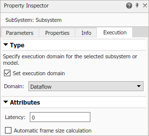
In the Execution tab of the Property Inspector, select the Set execution domain check box.
If the Property Inspector is not visible, in the Modeling tab, under Design, select Property Inspector. For more information on the Property Inspector, see Setting Model and Block Properties with Property Inspector (Simulink).
With the subsystem selected, set the Domain to
Dataflow.
Inside the subsystem, in the lower left corner of the model canvas, the
 icon indicates that the subsystem is a Dataflow
subsystem.
icon indicates that the subsystem is a Dataflow
subsystem.
Simulation of Dataflow Domains
Simulation of dataflow domains leverages the multicore CPU architecture of the host computer. It automatically partitions your model and simulates the subsystem using multiple threads.
The first time you simulate a dataflow domain, the simulation is single threaded. During this simulation, the software performs a cost analysis. The next time the model compiles, the software automatically partitions the system for multithreaded execution.
Each time you make a change inside the dataflow domain, the next simulation may be single threaded to allow the software to perform a new cost analysis. Following a cost analysis simulation, the next time the model compiles, the software repartitions the domain and subsequent simulations are multithreaded.
Some blocks and language features are not supported for multithreaded simulation. If a dataflow subsystem contains blocks or language features that do not support multithreaded simulation, Simulink® issues a warning and the subsystem always simulates in a single thread.
The To Workspace (Simulink) block and signal logging inside a Dataflow Subsystem block support multithreaded simulation. However, during multi-threaded execution, the output of the To Workspace block or logged signal data may be different than the single-threaded execution. This is because of the distribution of the pipeline delays inside the Dataflow Subsystem block for multithreading. These delays impact the output due to the latencies in the model. You can visualize these delays and the relationship between the output of the To Workspace block or the logged signals and the delays.
If a dataflow subsystem or model contains blocks or language features that are not supported inside a dataflow subsystem, Simulink generates an error. For more information, see Unsupported Simulink Software Features in Dataflow Domains.
Dataflow Parameters
Latency
To increase the throughput of a system, it can be advantageous to increase the latency of a system. Specify the Latency value in the Execution tab of the Property Inspector.
When latency is introduced into a dataflow domain, the output of the dataflow system is marked with a delay icon on the model canvas. Changes to the model within the dataflow subsystem may require a cost analysis and repartition.
![]()
To find the optimal latency settings for a Dataflow system or model, open the Performance Advisor. In the Performance Advisor > Simulation > Checks that Require Simulation to Run folder, run the Check Dataflow Domain Settings check.
For more information on types of parallelism in dataflow domains, see Multicore Simulation and Code Generation of Dataflow Domains.
You can also use the following settings for the optimal simulation performance. These settings are also provided in the toolstrip when you perform multicore analysis, see Perform Multicore Analysis for Dataflow.
Set Compiler optimization level (Simulink) to
Optimizations on (faster runs).set_param(gcs, 'SimCompilerOptimization', 'on')
Disable the Ensure responsiveness (Simulink) parameter.
set_param(gcs, 'SimCtrlC', 'off')
Set Wrap on overflow (Simulink) to
none.set_param(gcs, 'IntegerOverflowMsg', 'none')
Set Saturate on overflow (Simulink) to
none.set_param(gcs, 'IntegerSaturationMsg', 'none')
To further improve the simulation performance, follow the steps presented in Perform Multicore Analysis for Dataflow.
Automatic Frame Size Calculation
Simulink can automatically calculate the frame sizes needed for each block in a frame-based signal processing system, and insert buffers where needed. To enable automatic frame size calculation in a Dataflow system, select Automatic frame size calculation in the Execution tab of the Property Inspector.
![]()
Features Supported for Automatic Frame Size Calculation. Automatic frame size calculation is supported only for signals whose data types are one of the numeric types (built-in integer, double, single, or fixed-point). Signals using an enumerated type or whose data type is a bus are not supported.
Frame size calculation supports only two-dimensional signals.
Unsupported Simulink Software Features in Dataflow Domains
Dataflow domains do not support the following Simulink software features.
| Not Supported | Description |
|---|---|
| Referenced models | Model (Simulink) blocks are not supported in dataflow domains. |
| Nonvirtual Simulink subsystems, including Triggered Subsystem (Simulink), Enabled Subsystem (Simulink), and atomic subsystems | Only virtual subsystems are supported in dataflow domains. |
| Blocks with non-constant or non-inherited sample times | All sample times inside dataflow domains must be inherited
(-1), or constant (inf). |
| Continuous blocks | Blocks in the Continuous (Simulink) library are not supported in dataflow domains. Simulink indicates in the model canvas at edit-time that these blocks are not supported by highlighting the block in orange. |
| Data Store blocks | Data Store Memory, Data Store Read, and Data Store Write blocks are not supported inside dataflow domains. |
| Subset of Simulink blocks | If a dataflow domain contains blocks or language features that are not supported, Simulink generates an error when the model compiles. For some blocks, such as Scope blocks, Simulink indicates in the model canvas at edit-time that they are not supported by highlighting the block in orange. |
| Stateflow® charts | Stateflow charts are not supported inside dataflow domains. |
| SimEvents® blocks | SimEvents blocks are not supported inside dataflow domains. |
| Simscape™ blocks | Simscape blocks are not supported inside dataflow domains. |
| HDL code generation | Only C/C++ code generation is supported for models with dataflow domains. |