Biquad Filter
(To be removed) Model biquadratic IIR (SOS) filters
The Biquad Filter block will be removed in a future release. Use the Second-Order Section Filter block instead. The Second-Order Section Filter block has several advantages over the Biquad Filter block. For more information on key differences between the two blocks, see Difference Between Biquad Filter and Second-Order Section Filter Blocks.
Libraries:
DSP System Toolbox /
Filtering /
Filter Implementations
DSP System Toolbox HDL Support /
Filtering
Description
The Biquad Filter block independently filters each channel of the input signal with the specified biquadratic infinite impulse response (IIR) filter. When you specify the filter coefficients in the dialog box, the block implements static filters with fixed coefficients. When you provide the filter coefficients through an input port, you can tune the coefficients during simulation.
The Biquad Filter block supports the Simulink® state logging feature. See State (Simulink) for more information.
Examples
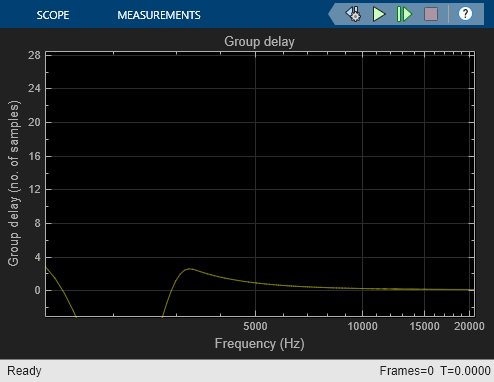
Group Delay Estimation in Simulink
Estimate the group delay of a filter in Simulink®.

Parametric Audio Equalizer
Model an algorithm specification for a three band parametric equalizer
Ports
Input
Output
Parameters
Main Tab
The Biquad Filter block can operate in three different modes:
Dialog parameters— Enter information about the filter, such as structure and coefficients, in the block mask.Input port(s)— Enter information about the filter structure in the block mask using the Filter structure parameter. The filter coefficients come into the block through additional input ports that appear on the block icon:Num— Specify numerator coefficients.Den— Specify denominator coefficients.g— Specify scale values.
The block assumes the first denominator coefficient of each section to be 1. This configuration applies when Coefficient source is set to
Input port(s)and Scale values mode is set toSpecify via input port (g).Filter object— Specify the filter using adsp.BiquadFilterSystem object™.
Specify the name of the discrete-time filter that you want the block to implement. You
must specify the filter as a dsp.BiquadFilter
System object.
You can define the System object in the block mask or in a MATLAB® workspace variable.
For information on creating System objects, see Define Basic System Objects.
Dependencies
This parameter is visible only when Coefficient source is set to
Filter object.
Specify the filter structure.
Dependencies
This parameter is visible only when Coefficient source is set to
Dialog parameters or Input
port(s).
Specify an M-by-6 matrix, where M is the number of sections in the second-order section filter. Each row of the SOS matrix contains the numerator and denominator coefficients (bik and aik) of the corresponding section in the filter.
The leading denominator coefficients [a01 a02 ... a0N] are treated as 1s, regardless of their actual values. No scaling is applied to the SOS matrix when a0 is not 1.
The ss2sos and tf2sos functions convert a state-space or transfer function description of your
filter into the second-order section description used by this block.
Dependencies
This parameter is visible only when Coefficient source is set to
Dialog parameters.
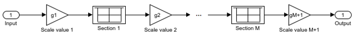
Specify scale values to be used between SOS sections. You can specify a real-valued scalar or a vector of length M+1:
When you enter a scalar, the value specifies the gain value before the first section of the second-order filter. The rest of the gain values default to 1.
When you enter a vector of M+1 values, each value specifies a separate section of the filter. For example, the first element is the first gain value, the second element is the second gain value, and so on.
Select the Optimize unity scale values check box to optimize your simulation when one or more scale values equal 1. Selecting this option removes the unity gains so that the values are treated like Simulink lines or wires. In some fixed-point cases when there are unity scale values, selecting this parameter also omits certain casts. Refer to the Fixed-Point Data Types section for more information.
Dependencies
This parameter is visible only when Coefficient source is set to
Dialog parameters.
Specify the initial conditions of the filter states when Filter
structure is set to Direct form II or
Direct form II transposed.
Direct form II

Direct form II transposed

The Biquad Filter block initializes the internal filter states to zero by default. To specify nonzero initial states for the filter delays, use the Initial conditions parameter.
To determine the number of initial conditions you must specify and how to specify them, see the following table on valid initial conditions.
Valid Initial Conditions
| Initial Condition | Description |
|---|---|
Scalar | The block initializes all delay elements in the filter to the scalar value. |
Vector or matrix | Each vector or matrix element specifies a unique initial condition for a corresponding delay element in a corresponding channel. M is the number of sections, and N is the number of input channels:
|
Dependencies
This parameter is only visible when Coefficient source is set to
Dialog parameters or Input port(s)
and the Filter structure is set to Direct form
II or Direct form II transposed.
Specify the initial conditions for the filter states on the side of the filter structure
with the zeros (b0,
b1, b2,
…). This parameter applies only when Filter structure is set to
Direct form I or Direct form I
transposed.
Direct form I

Direct form I
        transposed
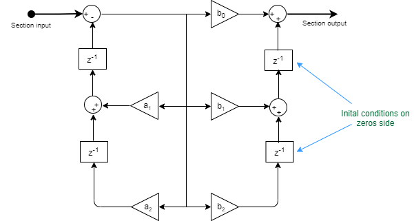
The Biquad Filter block initializes the internal filter states to zero by default. To specify nonzero initial states for the filter delays, use the Initial conditions on zeros side parameter.
To determine the number of initial conditions you must specify and how to specify them, see the following table on valid initial conditions.
Valid Initial Conditions
| Initial Condition | Description |
|---|---|
Scalar | The block initializes all delay elements in the filter to the scalar value. |
Vector or matrix | Each vector or matrix element specifies a unique initial condition for a corresponding delay element in a corresponding channel. Where M is the number of sections and N is the number of input channels:
|
Dependencies
This parameter is visible only when Coefficient source is set to
Dialog parameters or Input port(s)
and the Filter structure is set to Direct form
I or Direct form I transposed.
Specify the initial conditions for the filter states on the side of the filter structure
with the poles (a1,
a2, ...). This parameter applies only when
Filter structure is set to Direct form I or
Direct form I transposed.
Direct form
         I

Direct form I transposed

The Biquad Filter block initializes the internal filter states to zero by default. To specify nonzero initial states for the filter delays, use the Initial conditions on poles side parameter.
To determine the number of initial conditions you must specify and how to specify them, see the following table on valid initial conditions.
Valid Initial Conditions
| Initial Condition | Description |
|---|---|
Scalar | The block initializes all delay elements in the filter to the scalar value. |
Vector or matrix | Each vector or matrix element specifies a unique initial condition for a corresponding delay element in a corresponding channel. Where M is the number of sections and N is the number of input channels:
|
Dependencies
This parameter is visible only when Coefficient source is set to
Dialog parameters or Input port(s)
and the Filter structure is set to Direct form
I or Direct form I transposed.
Choose how to specify the scale values to use between filter sections. When you select
Specify via input port (g), you enter the scale values as a 2-D
vector at port g. When you select Assume all are unity and
optimize, all scale values are removed and treated like Simulink lines or
wires.
Dependencies
This parameter is visible only when Coefficient source is set to
Input port(s).
Specify the action the block should perform when the SOS matrix
a0j values do not equal one. The action can be
Warning, Error, or
None.
When you choose None, the leading coefficients
a0j are treated as 1's, regardless of their
actual values. No scaling is applied on the SOS matrix when a0 is not
1.
Dependencies
This parameter is visible only when Coefficient source is set to
Dialog parameters.
Select this check box to optimize your simulation when one or more scale values equal 1. Selecting this option removes the unity gains so that the values are treated like Simulink lines or wires. In some fixed-point cases when there are unity scale values, selecting this parameter also omits certain casts. See the Fixed-Point Data Types section for more information.
Dependencies
This parameter is visible only when Coefficient source is set to
Dialog parameters.
Specify how the block should process the input. If the input is an M-by-N matrix, you can set this parameter to:
Columns as channels (frame based)(default) — The block treats each column as a separate channel. In this mode, the block creates M instances of the same filter, each with its own independent state buffer. Each of the M filters process N input samples at every Simulink time step.Elements as channels (sample based)— The block treats each element as a separate channel. In this mode, the block creates MN instances of the same filter, each with its own independent state buffer. Each filter processes one input sample at every Simulink time step.
This button opens the Filter Visualization Tool (FVTool) and displays the filter response of the filter specified in the dialog.
Note
When you make changes to the filter parameters on the block dialog, you must click the Apply button before using the View Filter Response button.
Data Types Tab
Note
This tab appears only when you set Coefficient source to either
Dialog parameters or Input port(s). When
the Coefficient source is set to Filter object,
the data types specified in the filter object properties are used by the block.
Specify the rounding mode for fixed-point operations.
For more details, see rounding mode. The filter
coefficients do not obey this parameter; instead, they always round to
Nearest.
When you select this parameter, the block saturates the result of its fixed-point
operation. When you clear this parameter, the block wraps the result of its fixed-point
operation. For details on saturate and wrap, see overflow mode for fixed-point operations.
The filter coefficients are always saturated and do not obey this parameter.
Choose how you specify the word and fraction lengths of the fixed-point data type going into each section of a biquadratic filter. See the Fixed-Point Data Types section for illustrations depicting the use of the section input data type in this block. When you select:
Same as input— Word length and fraction length characteristics of the Section input data type match those of the input to the block.Binary point scaling— Enter the word and fraction lengths of the section input, in bits.
Choose how you specify the word and fraction lengths of the fixed-point data type coming out of each section of a biquadratic filter. See the Fixed-Point Data Types section for illustrations depicting the use of the section output data type in this block. When you select:
Same as section input— Word length and fraction length characteristics of the Section output data type match with those of the input to the block.Binary point scaling— Enter the word and fraction lengths of the section output, in bits.
Choose how you specify the word and fraction lengths of the multiplicand data type of a
Direct form I transposed filter structure. See the Fixed-Point Data Types section for illustrations
depicting the use of the multiplicand data type in this block.
When you select:
Same as output— Word length and fraction length characteristics of the Multiplicand data type match with those of the output of the block.Binary point scaling— Enter the word length and the fraction length of the multiplicand, in bits.
Dependencies
This parameter is visible only when the Filter structure parameter
is set to Direct form I transposed.
Choose how you specify the word and fraction lengths of the filter coefficients
(numerator, denominator, and scale value) when Coefficient source is set
to Dialog parameters. See the Fixed-Point Data Types section for illustrations
depicting the use of the coefficient data types in this block. When you select:
Same word length as input— Word length of the filter coefficients matches that of the input to the block. In this mode, the block automatically sets the fraction length of the coefficients to the binary point-only scaling that provides the best precision possible given the value and word length of the coefficients.Specify word length— Enter the word length of the coefficients, in bits. In this mode, the block automatically sets the fraction length of the coefficients to the binary point-only scaling that provides the best precision possible given the value and word length of the coefficients.Binary point scaling— Enter the word length and the fraction length of the coefficients, in bits. If applicable, enter separate fraction lengths for the numerator and denominator coefficients.
The filter coefficients do not obey the Rounding mode and the
Overflow mode parameters; instead, they are always saturated and
rounded to Nearest.
Dependencies
This parameter is visible only when Coefficient source is set to
Dialog parameters.
Specify how to designate the product output word and fraction lengths. See Multiplication Data Types and the Fixed-Point Data Types section for illustrations depicting the use of the product output data type in this block. When you select:
Same as input— Product output word length and fraction length characteristics match those of the input to the block.Inherit via internal rule— Product output word length and fraction lengths are computed based on full-precision rules. These rules prevent quantization from occurring within the block. Bits are added, as needed, so that no roundoff or overflow occurs. For more details, see Inherit via Internal Rule.Binary point scaling— Enter the word length and the fraction length of the product output, in bits. If applicable, enter separate fraction lengths for the numerator and denominator product output data type.
Specify how to designate the accumulator word and fraction lengths. See Multiplication Data Types and the Fixed-Point Data Types section for illustrations depicting the use of the accumulator data type in this block. When you select:
Same as input— Accumulator word and fraction length characteristics match those of the input to the block.Same as product output— Accumulator word and fraction length characteristics match those of the product output.Binary point scaling— Enter the word length and the fraction length of the accumulator, in bits. If applicable, enter separate fraction lengths for the numerator and denominator accumulator data type.
Specify how to designate the state word and fraction lengths when Coefficient
source is set to Dialog parameters. See the Fixed-Point Data Types section for illustrations
depicting the use of the state data type in this block.
When you select:
Same as input— State word and fraction length characteristics match those of the input to the block.Same as accumulator— State word and fraction length characteristics match those of the accumulator.Binary point scaling— Enter the word length and the fraction length of the state, in bits. If applicable, enter separate fraction lengths for the numerator and denominator state data type.
Dependencies
This parameter is visible only when Filter structure is set to
Direct form II or Direct form II
transposed.
Choose how you specify the output word length and fraction length. See the Fixed-Point Data Types section for illustrations depicting the use of the output data type in this block. When you select:
Same as input— Output word and fraction length characteristics match those of the input to the block.Same as accumulator— Output word and fraction length characteristics match those of the accumulator.Binary point scaling— Enter the word length and the fraction length of the output, in bits.
Select this parameter to prevent the fixed-point tools from overriding the data types you specify on the block mask.
Block Characteristics
Data Types |
|
Direct Feedthrough |
|
Multidimensional Signals |
|
Variable-Size Signals |
|
Zero-Crossing Detection |
|
More About
The diagrams in these sections show the filter structures supported by the Biquad Filter block. They also show the data types used in the filter structures for fixed-point signals. You can set the data types shown in these diagrams in the block dialog box.


The following diagram shows the data types for one section of the filter for fixed-point signals.

The following diagrams show the fixed-point data types between filter sections.
When the data is not optimized:

When you select Optimize unity scale values and scale values equal 1:


The following diagram shows the data types for one section of the filter for fixed-point signals.

The dashed casts are omitted when Optimize unity scale values is selected and scale values equal one.
The following diagrams show the fixed-point data types between filter sections.
When the data is not optimized:

When you select Optimize unity scale values and scale values equal 1:


The following diagram shows the data types for one section of the filter for fixed-point signals.

The following diagrams show the fixed-point data types between filter sections.
When the data is not optimized:

When you select Optimize unity scale values and scale values equal 1:
