FIR Interpolation
Perform polyphase FIR interpolation
Libraries:
DSP System Toolbox /
Filtering /
Multirate Filters
DSP System Toolbox HDL Support /
Filtering
Description
The FIR Interpolation block performs an efficient polyphase interpolation using an integer upsampling factor L along the first dimension.
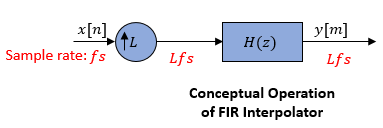
Conceptually, the FIR interpolator (as shown in the schematic) consists of an
upsampler followed by an FIR anti-imaging filter, which is usually an approximation of
an ideal band-limited interpolation filter. To design an FIR anti-imaging filter, use
the designMultirateFIR function. The upsampler
upsamples each channel of the input to a higher rate by inserting L–1
zeros between samples. The FIR filter that follows filters each channel of the upsampled
data. The resulting discrete-time signal has a sample rate that is L
times the original sample rate.
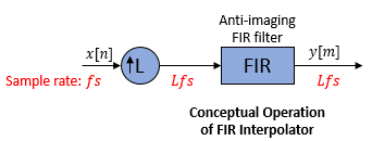
However, the actual block algorithm implements a direct-form FIR polyphase structure, an efficient equivalent of the combined system depicted in the diagram. For more details, see Algorithms.
You can use the FIR Interpolation block inside triggered subsystems when you set the
Rate options parameter to Enforce single-rate processing.
Under specific conditions, this block also supports SIMD code generation. For more details, see Code Generation.
Examples
FIR Interpolation Using Single-Rate Processing
Use FIR Interpolation block in single-rate processing mode.

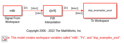
FIR Interpolation Using Multirate Frame-Based Processing
Use FIR Interpolation block in multirate frame-based processing mode.

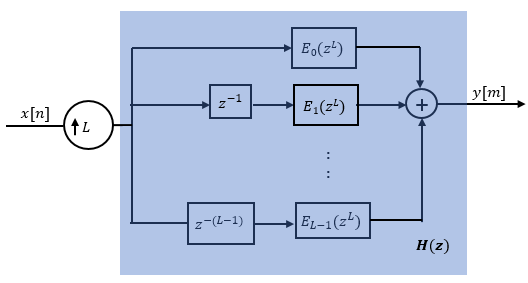
Polyphase Implementation of FIR Interpolation Block
Polyphase implementation of the FIR interpolator.
Two-Stage Multirate Narrow Lowpass Filter
Implement a two-stage multirate narrow band lowpass filter using FIR Decimation and FIR Interpolation blocks.
Ports
Input
Output
Parameters
Coefficient source
Specify the FIR filter coefficient source as one of the following:
Dialog parameters — Specify the filter coefficients through the FIR filter coefficients parameter in the block dialog box.
Input port — Specify the filter coefficients through the Num input port.
Filter object — Specify the filter using a
dsp.FIRInterpolatorSystem object™.Auto — When you select Auto, the block designs an FIR interpolator using the interpolation factor you specify in Interpolation factor. The
designMultirateFIRfunction designs the filter and returns the coefficients used by the block.For more information on the filter design, see Orfanidis [2].
Main Tab
Specify the numerator coefficients of the FIR filter transfer function H(z).
You can generate the FIR filter coefficient vector, b =
[b0,
b1, …,
bN], using one of the
DSP System Toolbox filter design functions such as designMultirateFIR, firnyquist, firgr or firceqrip.
To act as an effective anti-imaging filter, the coefficients usually
correspond to a lowpass filter with a normalized cutoff frequency no greater
than the reciprocal of the interpolation factor. To design such a filter,
use the designMultirateFIR
function.
The block internally initializes all filter states to zero.
Dependencies
This parameter appears only when you set the Coefficient source to Dialog parameters.
Data Types: single | double | int8 | int16 | int32 | int64 | uint8 | uint16 | uint32 | uint64
Complex Number Support: Yes
Specify the integer factor L. The block increases the sample rate of the input sequence by this factor.
Dependencies
This parameter appears only when you set the Coefficient source to Dialog parameters, Input port, or Auto.
Data Types: single | double | int8 | int16 | int32 | int64 | uint8 | uint16 | uint32 | uint64
Specify the name of the multirate filter object that you want the block to
implement. You must specify the filter as a dsp.FIRInterpolator
System object.
You can define the System object directly in the block dialog box. Alternatively, you can define the object in a MATLAB® workspace variable and specify the variable in the block dialog box.
For information on creating System objects, see Define Basic System Objects.
Dependencies
This parameter appears only when you set the Coefficient source to Filter object.
Specify how the block should process the input. You can set this parameter to one of the following options:
Columns as channels (frame based)— When you select this option, the block treats each column of the input as a separate channel.Elements as channels (sample based)— When you select this option, the block treats each element of the input as a separate channel.
Specify the method by which the block should interpolate the input. You can select one of the following options:
Enforce single-rate processing— When you select this option, the block maintains the input sample rate, and interpolates the signal by increasing the output frame size by a factor of L. To select this option, you must set the Input processing parameter toColumns as channels (frame based).Allow multirate processing— When you select this option, the block interpolates the signal such that the output sample rate is L times faster than the input sample rate.
When you set the Rate options parameter to
Allow multirate processing and run your
models in Simulink®
MultiTasking mode, the block exhibits latency. The amount
of latency for multirate, multitasking operation depends on how you set the
Input processing parameter.
| Input processing | Latency |
|---|---|
| L samples |
| L frames (Ki samples per frame) |
When the block exhibits latency, the default initial condition is zero. Alternatively, you can use the Output buffer initial conditions parameter to specify a matrix of initial conditions containing one value for each channel or a scalar initial condition that the block applies to all channels. The block divides the Output buffer initial conditions by the Interpolation factor and outputs the scaled initial conditions until the first filtered input sample becomes available.
Output buffer initial conditions are stored in the output data type and scaling.
See Latency for more information about latency in the FIR Interpolation block.
Dependencies
This parameter appears only when you configure the block to perform
multirate processing by setting Rate options to
Allow multirate processing.
Data Types: single | double | int8 | int16 | int32 | int64 | uint8 | uint16 | uint32 | uint64
Complex Number Support: Yes
Click on this button to open the Filter Visualization Tool (fvtool) and display the filter response of the filter
defined in the block dialog box.
Data Types Tab
Select the rounding
mode for fixed-point operations. The default is
Floor. The filter coefficients do not obey
this parameter and always round to
Nearest.
Note
The Rounding mode and Saturate on integer overflow settings have no effect on numerical results when all the following conditions exist:
Product output is
Inherit: Inherit via internal
											rule
Accumulator is
Inherit:
											Inherit via internal rule
Output is
Inherit: Same
											as accumulator
With these data type settings, the block is effectively operating in the full-precision mode.
When you select this parameter, the block saturates the result of its
fixed-point operation. When you clear this parameter, the block wraps the
result of its fixed-point operation. For details on
saturate and wrap, see overflow
mode for fixed-point operations.
Note
The Rounding mode and Saturate on integer overflow parameters have no effect on numeric results when all these conditions are met:
Product output data type is
Inherit: Inherit via internal rule.Accumulator data type is
Inherit: Inherit via internal
											rule
.
With these data type settings, the block operates in the full-precision mode.
Specify the coefficients data type. See Fixed-Point Data Types and Multiplication Data Types for illustrations depicting the use of the coefficients data type in this block.
You can set this parameter to one of the following:
Inherit: Same word length as inputfixdt(1,16,0)orfixdt(1,16)— Specify a data type object.
Click the Show data type assistant button
![]() to display the Data Type
Assistant, which helps you set the
Coefficients parameter.
to display the Data Type
Assistant, which helps you set the
Coefficients parameter.
See Specify Data Types Using Data Type Assistant (Simulink) for more information.
Dependencies
This parameter appears only when you set Coefficient
source to Dialog parameters,
Filter object, or
Auto.
When Coefficient source is set to
Filter object,
Coefficients parameter is automatically set to
Same word length as input.
Specify the minimum value of the filter coefficients. The default value is
[] (unspecified). Simulink software uses this value to perform automatic scaling of
fixed-point data types.
Dependencies
This parameter appears only when you set Coefficient
source to Dialog parameters or
Auto.
Specify the maximum value of the filter coefficients. The default value is
[] (unspecified). Simulink software uses this value to perform automatic scaling of
fixed-point data types.
Dependencies
This parameter appears only when you set Coefficient
source to Dialog parameters or
Auto.
Specify the product output data type. See Fixed-Point Data Types and Multiplication Data Types for illustrations depicting the use of the product output data type in this block.
You can set this parameter to one of the following:
Inherit: Inherit via internal
								rule
For more information on this rule, see Inherit via Internal Rule.
Inherit: Same as inputfixdt(1,16,0)— Specify a data type object.
Click the Show data type assistant button
![]() to display the Data Type
Assistant, which helps you set the Product
output parameter.
to display the Data Type
Assistant, which helps you set the Product
output parameter.
See Specify Data Types Using Data Type Assistant (Simulink) for more information.
Dependencies
When Coefficient source is set to
Filter object, Product
output parameter is automatically set to Full
precision.
Specify the accumulator data type. See Fixed-Point Data Types for illustrations depicting the use of the accumulator data type in this block.
You can set this parameter to one of the following:
Inherit: Inherit via internal rule.For more information on this rule, see Inherit via Internal Rule.
Inherit: Same as inputInherit: Same as product outputfixdt(1,16,0)— Specify a data type object.
Click the Show data type assistant button
![]() to display the Data Type
Assistant, which helps you set the
Accumulator parameter.
to display the Data Type
Assistant, which helps you set the
Accumulator parameter.
See Specify Data Types Using Data Type Assistant (Simulink) for more information.
Dependencies
When Coefficient source is set to
Filter object,
Accumulator parameter is automatically set to
Full
								precision
.
Specify the output data type. See Fixed-Point Data Types for illustrations depicting the use of the output data type in this block.
You can set it to one of the following:
Inherit: Same as accumulatorInherit: Same as inputInherit: Same as product outputfixdt(1,16,0)— Specify a data type object.
Click the Show data type assistant button
![]() to display the Data Type
Assistant, which helps you set the
Output parameter.
to display the Data Type
Assistant, which helps you set the
Output parameter.
See Control Data Types of Signals (Simulink) for more information.
Dependencies
When Coefficient source is set to
Filter object,
Output parameter is automatically set to
Same as accumulator.
Specify the minimum value that the block should output. The default value
is [] (unspecified). Simulink software uses this value to perform:
Simulation range checking (see Specify Signal Ranges (Simulink))
Automatic scaling of fixed-point data types
Dependencies
This parameter appears only when you set Coefficient
source to Dialog parameters,
Input port, or
Auto.
Specify the maximum value that the block should output. The default value
is [] (unspecified). Simulink software uses this value to perform:
Simulation range checking (see Specify Signal Ranges (Simulink))
Automatic scaling of fixed-point data types
Dependencies
This parameter appears only when you set Coefficient
source to Dialog parameters,
Input port, or
Auto.
Block Characteristics
Data Types |
|
Direct Feedthrough |
|
Multidimensional Signals |
|
Variable-Size Signals |
|
Zero-Crossing Detection |
|
More About
The following diagram shows the data types used within the FIR Interpolation block for fixed-point signals.
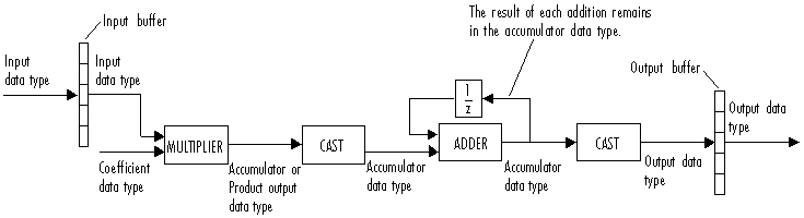
This diagram shows that input data is stored in the input buffer with the same data type and scaling as the input. The block stores filtered data and any initial conditions in the output buffer using the output data type and scaling that you set in the block dialog box.
When at least one of the inputs to the multiplier is real, the output of the multiplier is in the product output data type. When both inputs to the multiplier are complex, the result of the multiplication is in the accumulator data type. For details on the complex multiplication performed by this block, see Multiplication Data Types.
Note
When the block input is fixed point, all internal data types are signed fixed point.
Algorithms
The FIR interpolation filter is implemented efficiently using a polyphase structure.
To derive the polyphase structure, start with the transfer function of the FIR filter:
N+1 is the length of the FIR filter.
You can rearrange this equation as follows:
L is the number of polyphase components, and its value equals the interpolation factor that you specify.
You can write this equation as:
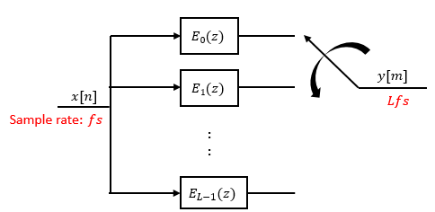
E0(zL), E1(zL), ..., EL-1(zL) are polyphase components of the FIR filter H(z).
Conceptually, the FIR interpolation filter contains an upsampler followed by an FIR lowpass filter H(z).
Replace H(z) with its polyphase representation.
Here is the multirate noble identity for interpolation.
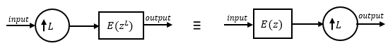
Applying the noble identity for interpolation moves the upsampling operation to after the filtering operation. This move enables you to filter the signal at a lower rate.
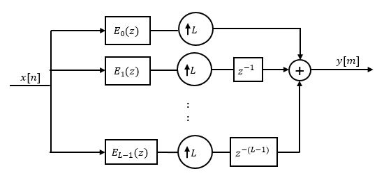
You can replace the upsampling operator, delay block, and adder with a commutator switch. The switch starts on the first branch 0 and moves in the counterclockwise direction, each time receiving one sample from each branch. The interpolator effectively outputs L samples for every one input sample it receives. Hence the sample rate at the output of the FIR interpolation filter is Lfs.
References
[1] Fliege, N. J. Multirate Digital Signal Processing: Multirate Systems, Filter Banks, Wavelets. West Sussex, England: John Wiley & Sons, 1994.
[2] Orfanidis, Sophocles J. Introduction to Signal Processing. Upper Saddle River, NJ: Prentice-Hall, 1996.
Extended Capabilities
Version History
Introduced before R2006aSee Also
Functions
firgr|firceqrip|firnyquist
Objects
Blocks
- Variable FIR Interpolation | Upsample | FIR Decimation | FIR Rate Conversion | FIR Halfband Interpolator | FIR Halfband Decimator | IIR Halfband Interpolator | IIR Halfband Decimator | CIC Compensation Interpolator | CIC Compensation Decimator | Upsample | CIC Interpolation | Digital Down-Converter | Digital Up-Converter