addResponse
R2026bDescription
addResponse( adds
the response for dynamic system model
rp,sys)sys to the existing response plot associated with chart object
rp.
The time and frequency specifications for the added response are computed automatically.
The line width and color for the response are assigned automatically.
addResponse(___,
configures added responses using one or more name-value arguments. For example,
Name=Value)addResponse(rp,sys,LineWidth=1) adds the response for model
sys and sets the plot line width to 1.
When adding responses for multiple systems, the specified name-value arguments apply to all responses.
Examples
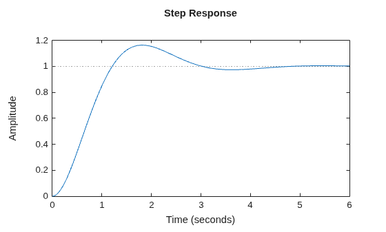
Create a second-order transfer function with a damping ratio of 0.5.
wn = 2;
zeta = 0.5;
sys = tf(wn^2,[1,2*zeta*wn,wn^2]);
Plot the step response of this system.
sp = stepplot(sys);
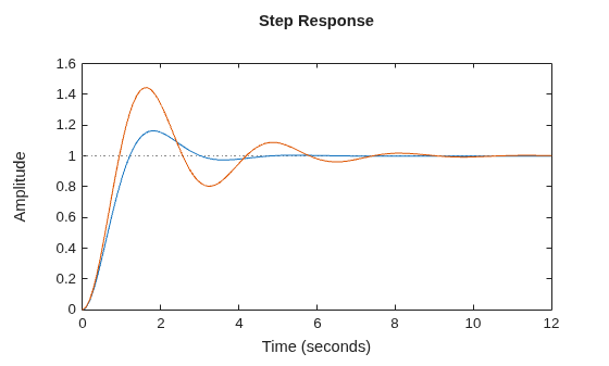
Create a transfer function with a lower damping ratio and add it to the step plot.
zetaL = 0.25;
sysL = tf(wn^2,[1,2*zetaL*wn,wn^2]);
addResponse(sp,sysL);
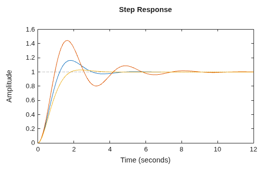
Create a transfer function with a higher damping ratio and add it to the step plot.
zetaH = 0.75;
sysH = tf(wn^2,[1,2*zetaH*wn,wn^2]);
addResponse(sp,sysH);
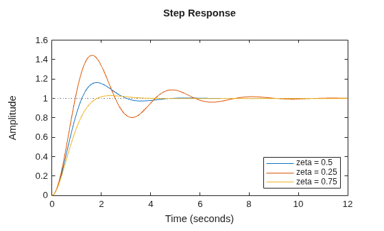
Add a legend to the plot.
legend("zeta = 0.5","zeta = 0.25","zeta = 0.75",...
    Location="southeast");
Input Arguments
Response plot chart, specified as an object created using one of these functions:
impulseplot— Impulse responseinitialplot— Initial condition responsestepplot— Step responselsimplot— Simulated time response to arbitrary inputbodeplot— Bode frequency responsenicholsplot— Nichols frequency responsenyquistplot— Nyquist responsesigmaplot— Singular values for frequency responsepzplot— Pole-zero mapiopzplot— Plot pole-zero map for input-output pairsrlocusplot— Root locus plotpassiveplot— Passivity indices (since R2026b)sectorplot— Sector indices (since R2026b)
Dynamic system, specified as a SISO or MIMO dynamic system model or array of dynamic system models. Dynamic systems that you can use include:
Continuous-time or discrete-time numeric LTI models, such as
tf,zpk, orssmodels.Generalized or uncertain LTI models such as
genssoruss(Robust Control Toolbox) models. Using uncertain models requires Robust Control Toolbox™ software.For tunable control design blocks, the function evaluates the model at its current value to plot the response.
For uncertain control design blocks, the function plots the nominal value and random samples of the model.
Frequency-response data models such as
frdmodels. For such models, the function plots the response at the frequencies defined in the model.Identified LTI models, such as
idtf(System Identification Toolbox),idss(System Identification Toolbox), oridproc(System Identification Toolbox) models. Using identified models requires System Identification Toolbox™ software.Linear time-varying (
ltvss) and linear parameter-varying (lpvss) models.
Dependencies
The supported models depend on the type of chart object specified in
rp.
Frequency-response data models are supported only for
bodeplot,nicholsplot,nyquistplot, andsigmaplotchart objects.Linear time-varying and linear parameter-varying models are supported only for
stepplot,impulseplot,initialplot, andlsimplotchart objects.For
rlocusplotchart objects, only SISO models are supported.
Name-Value Arguments
Specify optional pairs of arguments as
Name1=Value1,...,NameN=ValueN, where Name is
the argument name and Value is the corresponding value.
Name-value arguments must appear after other arguments, but the order of the
pairs does not matter.
Example: addResponse(rp,sys,Color="red") adds a response and sets its
color to red.
Plot Appearance
Response name, specified as a string or character vector and stored as a string.
Response visibility, specified as one of these logical on/off values:
"on",1, ortrue— Display the response in the plot."off",0, orfalse— Do not display the response in the plot.
The value is stored as an on/off logical value of type matlab.lang.OnOffSwitchState.
Option to list the response in the legend, specified as one of these logical on/off values:
"on",1, ortrue— List the response in the legend."off",0, orfalse— Do not list the response in the legend.
The value is stored as an on/off logical value of type matlab.lang.OnOffSwitchState.
Marker style, specified as one of these values. Specifying a marker style using a
name-value argument overrides any marker style that you specify using
LineSpec.
| Marker | Description |
|---|---|
"none" | No marker |
"o" | Circle |
"+" | Plus sign |
"*" | Asterisk |
"." | Point |
"x" | Cross |
"_" | Horizontal line |
"|" | Vertical line |
"s" | Square |
"d" | Diamond |
"^" | Upward-pointing triangle |
"v" | Downward-pointing triangle |
">" | Right-pointing triangle |
"<" | Left-pointing triangle |
"p" | Pentagram |
"h" | Hexagram |
Dependencies
The MarkerStyle argument is not supported for
pzplot or iopzplot responses.
Plot color, specified as an RGB triplet or a hexadecimal color code and stored as an RGB triplet.
Alternatively, you can specify some common colors by name. This table lists these colors and their corresponding RGB triplets and hexadecimal color codes.
| Color Name | RGB Triplet | Hexadecimal Color Code |
|---|---|---|
| [1 0 0] | #FF0000 |
| [0 1 0] | #00FF00 |
| [0 0 1] | #0000FF |
| [0 1 1] | #00FFFF |
| [1 0 1] | #FF00FF |
| [1 1 0] | #FFFF00 |
| [0 0 0] | #000000 |
| [1 1 1] | #FFFFFF |
Line style, specified as one of these values.
| Line Style | Description |
|---|---|
"-" | Solid line |
"--" | Dashed line |
":" | Dotted line |
"-." | Dash-dotted line |
"none" | No line |
Dependencies
The LineStyle argument is not supported for
pzplot or iopzplot responses.
Marker size, specified as a positive scalar.
Line width, specified as a positive scalar.
Series index, specified as a positive integer or "none".
By default, the SeriesIndex property is a number that
corresponds to the order in which the response was added to the chart, starting at 1.
MATLAB® uses the number to calculate indices for automatically assigning color,
line style, or markers for responses. Any responses in the chart that have the same
SeriesIndex number also have the same color, line style, and
markers.
A SeriesIndex value of "none" indicates
that a response does not participate in the indexing scheme.
Plot options, specified as one of the following objects, depending on the type of
chart object specified in rp.
| Options Object | Chart Object rp |
|---|---|
timeoptions | impulseplot, initialplot,
stepplot, and lsimplot |
bodeoptions | bodeplot |
nicholsoptions | nicholsplot |
nyquistoptions | nyquistplot |
sigmaoptions | sigmapplot |
pzoptions | pzplot, iopzplot, and
rlocusplot |
| passiveplot and sectorplot |
Time-Domain Response
Time steps at which to compute the response, specified as one of the following:
Positive scalar
tFinal— Compute the response fromt = 0tot = tFinal.Two-element vector
[t0
                    tFinal]
— Compute the response fromt = t0tot = tFinal. (since R2023b)Vector
Ti:dt:Tf— Compute the response for the time points specified int.For continuous-time systems,
dtis the sample time of a discrete approximation to the continuous system.For discrete-time systems with a specified sample time,
dtmust match the sample time propertyTsofsys.For discrete-time systems with an unspecified sample time (
Ts = -1),dtmust be1.
[]— Automatically select time values based on system dynamics.
When you specify a time range using either tFinal or
[t0 tFinal]:
For continuous-time systems, the function automatically determines the size of the time step and number of points based on the system dynamics.
For discrete-time systems with a specified sample time, the function uses the sample time of
sysas the step size.For discrete-time systems with unspecified sample time (
Ts =
                    -1
), the function interpretstFinalas the number of sampling periods to simulate with a sample time of 1 second.
Express t using the time units specified in the
TimeUnit property of sys.
If you specified a step delay td using
Config, the function applies the step at t =
t0+td.
Dependencies
This argument is supported only when rp is one of the
following objects:
stepplotimpulseplotinitialplotlsimplot
Parameter trajectory of the LPV model, specified as a matrix or a function handle.
For exogenous or explicit trajectories, specify
pas a matrix with dimensions N-by-Np, where N is the number of time samples and Np is the number of parameters.Thus, the row vector
p(i,:)contains the parameter values at the ith time step.For endogenous or implicit trajectories, specify
pas a function handle of the form p = F(t,x,u) in continuous time and p = F(k,x,u) in discrete time that gives parameters as a function of time t or time sample k, state x, and input u.This option is useful when you want to simulate quasi-LPV models. For an example, see Step Response of LPV Model.
Dependencies
This argument is supported only when sys is an LPV model
and rp is a stepplot object or an
impulseplot object.
Dependencies
This argument is supported only when rp is one of the
following objects:
stepplotimpulseplotinitialplotlsimplot
Initial condition, specified as one of these values:
[]— Start simulation from the steady-state condition for the input value specified inBias. For state-space models without internal delays, the initial state xinit is the solution to the following, where U is theBiasvalue:Continuous time — 0 = A xinit + B U
Discrete time — xinit = A xinit + B U
Vector of initial state values with length equal to the number of states in the model — Start simulation from the specified initial state and use
Biasas the initial input value."x0"— UseBiasas the initial input value and evaluate state offset value x 0 for state-space models, x 0(T 0) for LTV models, or x 0(T 0,p(T 0)) for LPV models. For LTV and LPV models, the state offset value is thex0output of the data function evaluated at t = T 0.initialCondition(System Identification Toolbox) object for identified models (requires System Identification Toolbox software) — Start simulation from the specified initial state and useBiasas the initial input value.Operating condition created using
findop— An operating point object allows you to start the simulation from a steady-state operating condition with nonzero past u, w, and y values. When you specify an operating point object, the value ofBiasis ignored.
Since R2026b
Input level change relative to the input signal bias, specified as a scalar or vector.
For single-input systems,
Amplitudeis a scalar value.For multi-input systems,
Amplitudeis a vector of length N u, where N u is the number of input channels. Each vector value corresponds to the level change amplitude in that input channel. The functions compute the responses one input channel at a time.For complex systems, you can specify a complex step amplitude. (since R2025a)
Dependencies
This argument is supported only when rp is a
stepplot object or an impulseplot object.
Since R2026b
Baseline input signal value, specified as a scalar or vector.
For single-input systems,
Biasis a scalar value.For multi-input systems,
Biasis a vector of length N u, where N u is the number of input channels. Each vector value corresponds to the signal value in that input channel. The functions compute the responses one input channel at a time.For state-space models with offsets, set
Bias="u0"to apply the step or impulse change relative to the model offsets u 0, u 0(t) of the LTV model, or u 0(t,p) of the LPV model. For LTV and LPV models, this is theu0output of the data function. The total input signal is then u 0 + u(t).
Dependencies
This argument is supported only when rp is a
stepplot object or an impulseplot object.
Since R2026b
Input signal delay, specified as a nonnegative scalar value. This value specifies when the change occurs relative to the simulation start time T 0.
Dependencies
This argument is supported only when rp is a
stepplot object or an impulseplot object.
Discretization interpolation method for sampling continuous-time models, specified as one of the following.
"zoh"— Zero-order hold"foh"— First-order hold
When sys is a continuous-time model,
lsimplot computes the time response by discretizing the model
using a sample time equal to the time step dT = t(2)-t(1) of
t. If you do not specify a discretization method, then
lsimplot selects the method automatically based on the
smoothness of the signal u. For more information about these two
discretization methods, see Continuous-Discrete Conversion Methods.
Dependencies
This argument is supported only when rp is an
lsimplot object.
Frequency-Domain Response
Frequencies at which to compute the response, specified as one of the following:
Cell array of the form
{wmin,wmax}— Compute the response at frequencies in the range fromwmintowmax. Ifwmaxis greater than the Nyquist frequency ofsys, the response is computed only up to the Nyquist frequency.Vector of frequencies — Compute the response at each specified frequency. For example, use
logspaceto generate a row vector with logarithmically spaced frequency values. The vectorwcan contain both positive and negative frequencies.[]— Automatically select frequencies based on system dynamics.
For models with complex coefficients, if you specify a frequency range of [wmin,wmax] for your plot, then in:
Log frequency scale, the plot frequency limits are set to [wmin,wmax] and the plot shows two branches, one for positive frequencies [wmin,wmax] and one for negative frequencies [–wmax,–wmin].
Linear frequency scale, the plot frequency limits are set to [–wmax,wmax] and the plot shows a single branch with a symmetric frequency range centered at a frequency value of zero.
Specify frequencies in units of rad/TimeUnit, where
TimeUnit is the TimeUnit property of the
model.
Dependencies
This argument is supported only when rp is a
bodeplot,nicholsplot,
nyquistplot, sigmaplot,
passiveplot, or sectorplot object.
Type of modified singular values to plot, specified as one of the following values.
1— Plot the singular values of the frequency response H-1, where H is the frequency response ofsys.2— Plot the singular values of the frequency response I+H.3— Plot the singular values of the frequency response I+H-1.
Dependencies
This argument is supported only when
rpis asigmaplotobject.You can specify
SingularValueTypeonly whensyshas the same number of inputs and outputs.
Root Locus Plot
Feedback gain values that pertain to pole locations, specified as a vector. The feedback gains define the trajectory of the poles thereby affecting the shape of the root locus plot.
Dependencies
This argument is supported only when rp is an
rlocusplot object.
Passivity Plots
Since R2026b
Type of passivity index, specified as one of the following:
"input"— Input passivity index (input feedforward passivity). This value is the smallest eigenvalue of , for s = jω in continuous time, and s = ejω in discrete time."output"— Output passivity index (output feedback passivity). WhenGis minimum phase, this value is the smallest eigenvalue of , for s = jω in continuous time, and s = ejω in discrete time."io"— Combined I/O passivity index. WhenI + Gis minimum phase, this value is the largest τ(ω) such that:for s = jω in continuous time, and s = ejω in discrete time.
See About Passivity and Passivity Indices for details about these indices.
Dependencies
This argument is supported only when rp is a
passiveplot object.
Since R2026b
Sector geometry, Q, specified as:
A matrix, for constant sector geometry.
Qis a symmetric square matrix that isnyon a side, wherenyis the number of outputs ofH.An LTI model, for frequency-dependent sector geometry.
Qsatisfies Q(s)’ = Q(–s). In other words, Q(s) evaluates to a Hermitian matrix at each frequency.
The matrix Q must be indefinite to describe a well-defined
conic sector. An indefinite matrix has both positive and negative eigenvalues.
For more information, see About Sector Bounds and Sector Indices.
Dependencies
This argument is supported only when rp is a
sectorplot object.
Version History
Introduced in R2024bYou can now specify response options using these name-value arguments:
Bias— Baseline input signal valueAmplitude— Input level changeDelay— Input signal delayInitialCondition— System initial condition
These properties replace response configuration using a RespConfig
object. For more information, see Setting response options using RespConfig object not recommended.
Setting response options for stepplot and impulseplot
objects using the Config name-value argument is not recommended. Use
the Bias, Amplitude, Delay,
and InitialCondition name-value arguments instead.
See Also
impulseplot | initialplot | stepplot | lsimplot | bodeplot | nicholsplot | nyquistplot | sigmaplot | pzplot | iopzplot | rlocusplot
MATLAB Command
You clicked a link that corresponds to this MATLAB command:
Run the command by entering it in the MATLAB Command Window. Web browsers do not support MATLAB commands.


Website auswählen
Wählen Sie eine Website aus, um übersetzte Inhalte (sofern verfügbar) sowie lokale Veranstaltungen und Angebote anzuzeigen. Auf der Grundlage Ihres Standorts empfehlen wir Ihnen die folgende Auswahl: .
Sie können auch eine Website aus der folgenden Liste auswählen:
So erhalten Sie die bestmögliche Leistung auf der Website
Wählen Sie für die bestmögliche Website-Leistung die Website für China (auf Chinesisch oder Englisch). Andere landesspezifische Websites von MathWorks sind für Besuche von Ihrem Standort aus nicht optimiert.
Amerika
- América Latina (Español)
- Canada (English)
- United States (English)
Europa
- Belgium (English)
- Denmark (English)
- Deutschland (Deutsch)
- España (Español)
- Finland (English)
- France (Français)
- Ireland (English)
- Italia (Italiano)
- Luxembourg (English)
- Netherlands (English)
- Norway (English)
- Österreich (Deutsch)
- Portugal (English)
- Sweden (English)
- Switzerland
- United Kingdom (English)