FIR Halfband Decimator
Decimate signal using polyphase FIR halfband filter
Libraries:
DSP System Toolbox /
Filtering /
Multirate Filters
Description
The FIR Halfband Decimator block performs polyphase decimation of the input signal by a factor of 2. The block uses an FIR equiripple design or a Kaiser window design to construct the halfband filters. The implementation takes advantage of the zero-valued coefficients of the FIR halfband filter, making one of the polyphase branches a delay. You can use the block to implement the analysis portion of a two-band filter bank to separate a signal into lowpass and highpass subbands. For more information, see Algorithms.
The block supports fixed-point operations and ARM® Cortex® code generation. For more information on ARM Cortex code generation, see Code Generation for ARM Cortex-M and ARM Cortex-A Processors.
Examples
Since R2023b
Design and implement an FIR halfband decimator using the FIR Halfband Decimator block. Pass a noisy input through the decimator. Plot the spectrum of the input and the decimated subband outputs in the spectrum analyzer.
This example also shows how to use the Allow arbitrary frame length for fixed-size input signals parameter.
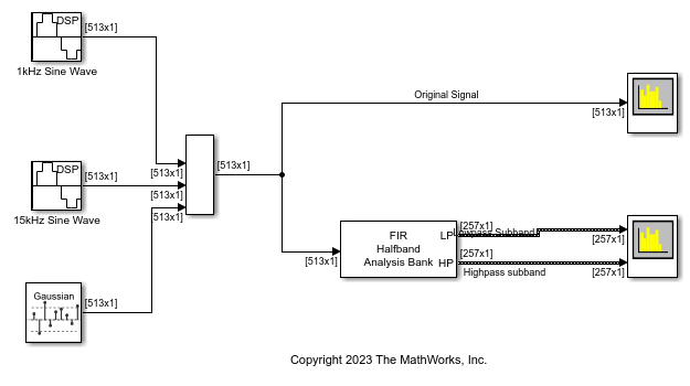
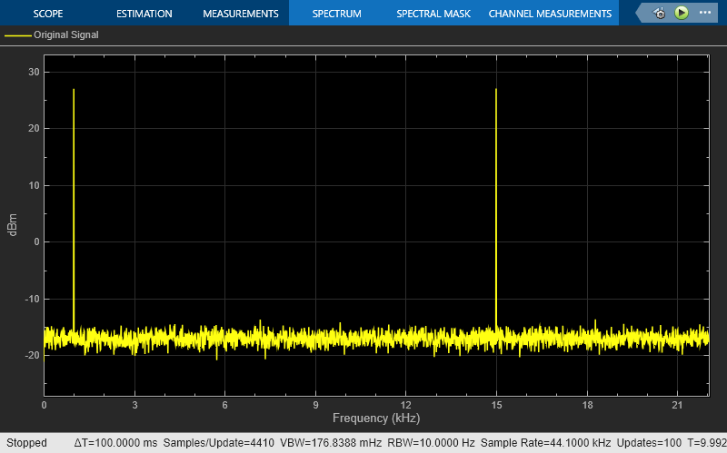
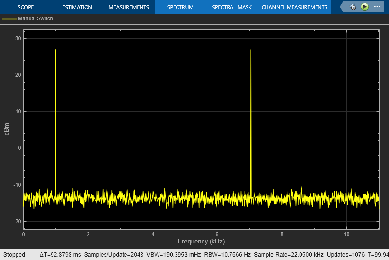
Open and inspect the DesignAndImplementFIRHalfbandDecimator model. The input signal in the model is a noisy sinusoidal signal with 513 samples per frame and contains two frequencies, one at 1 kHz and the other at 15 kHz. The Random Source block adds white Gaussian noise with a mean of 0 and a variance of 0.05 to this signal. The input signal is a fixed-size signal, that is, the frame length of the signal (513 samples per frame) does not vary during simulation.
To allow an arbitrary frame length for a fixed-size signal, that is, to allow a frame length that is not a multiple of the decimation factor 2, select the Allow arbitrary frame length for fixed-size input signals parameter in FIR Halfband Decimator block dialog box.
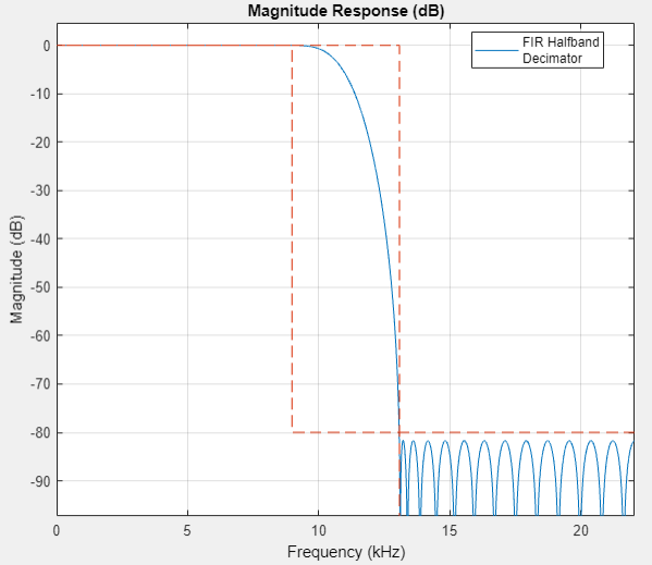
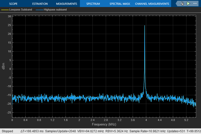
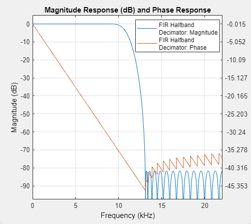
The FIR halfband decimator has a transition width of 4.1 kHz and a stopband attenuation of 80 dB. The decimator outputs the highpass subband signal.
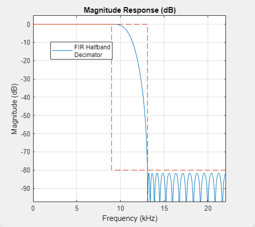
Visualize the magnitude response of the filter by clicking the View Filter Response button in the block dialog box.
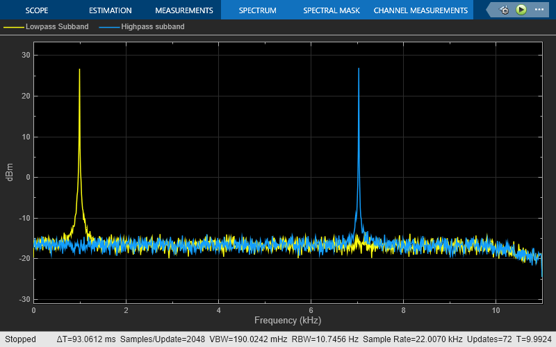
Pass the noisy sinusoidal signal through the decimator. Plot the spectrum of the input and the lowpass and highpass subband outputs in two separate spectrum analyzer windows.
The block allows arbitrary frame lengths for variable-size signals irrespective of the setting of the Allow arbitrary frame length for fixed-size input signals parameter. When the input is a variable-size signal, the frame length of the signal can vary during simulation.
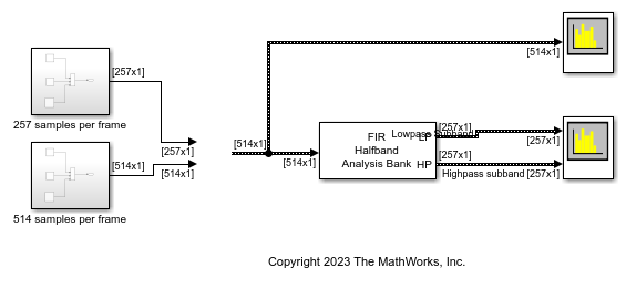
Open the DesignAndImplementFIRHalfbandDecimator_Varsize model. The input is a variable-size signal. The input frame length can vary between 257 and 514 samples per frame.
Since R2023b
Use the FIR Halfband Decimator and FIR Halfband Interpolator blocks to extract and reconstruct the low-frequency subband from a speech signal.
Open and inspect the ExtractLowFrequencySubbandFromSpeechFIR.slx model. The input audio data is a single-channel speech signal with the sample rate of 22050 Hz.
Specify the Sample rate mode parameter of the FIR Halfband Decimator and FIR Halfband Interpolator blocks to Use normalized frequency (0 to 1). This option enables you to specify the transition width of the decimation and interpolation filters in normalized frequency units. Set the transition width to 0.093 in normalized frequency units and the stopband attenuation to 80 dB. The design method is set to Auto by default. In the Auto mode, the block selects the equiripple or Kaiser window design method based on the design parameters of the filter.
Read the speech signal from the audio file in frames of 1024 samples. The FIR Halfband Decimator block extracts and outputs the lowpass subband of the speech signal. The FIR Halfband Interpolator block reconstructs the lowpass approximation of the speech signal by interpolating the lowpass subband.
The Audio Device Writer block plays the filtered output.

Use the FIR Halfband Decimator and FIR Halfband Interpolator blocks to implement a two-channel filter bank. This example uses an audio file input and shows that the power spectrum of the filter bank output does not differ significantly from the input. Play the output of the filter bank using the Audio Device Writer block.
Open and inspect the TwoChannelFIRFilterBank.slx model. The input audio data is a single-channel speech signal with a sample rate of 22050 Hz.
The FIR Halfband Decimator block acts as an FIR halfband analysis bank as the Output highpass subband parameter is selected in the block dialog box. The FIR Halfband Interpolator block acts as an FIR halfband synthesis bank as the Input highpass subband parameter is selected in the block dialog box.
Set the Sample rate mode parameter in the FIR Halfband Decimator and FIR Halfband Interpolator blocks to Inherit from input port so that the blocks inherit the sample rate from the respective input ports. Set the transition width to 4.1 kHz and the stopband attenuation to 80 dB. The design method is set to Auto by default. In the Auto mode, the block selects the equiripple or Kaiser window design methods based on the design parameters of the filter.
Read the speech signal from the audio file in frames of 1024 samples. The FIR halfband analysis bank extracts the lowpass and highpass subbands of the speech signal. The FIR halfband synthesis filter bank synthesizes the speech signal from the lowpass and highpass subbands.
Display the power spectrum of the audio input and the output of the synthesis filter bank in the spectrum analyzer. Play the synthesized speech signal using the Audio Device Writer block.


Ports
Input
Output
Parameters
Main Tab
Select the parameters that the block uses to design the FIR halfband filter.
Transition width and stopband
								attenuation
(default) — Design the filter using Transition width (Hz) and Stopband attenuation (dB). This design is the minimum-order design.Filter order and transition width— Design the filter using Filter order and Transition width (Hz).Filter order and stopband attenuation— Design the filter using Filter order and Stopband attenuation (dB).Coefficients— Specify the filter coefficients directly through the Numerator parameter.
Specify the filter order as an even positive integer.
Dependencies
To enable this parameter, set Filter
specification to Filter order and
transition width or Filter order and
stopband attenuation.
Specify the transition width as a positive scalar in Hz or in normalized frequency units (since R2023b).
If you set the Sample rate mode parameter to:
Specify on dialogorInherit from input port— The value of the transition width is in Hz and must be less than half the value of the input sample rate.Use normalized frequency (0 to 1)— The value of the transition width is in normalized frequency units. The value must be a positive scalar less than1.0.
(since R2023b)
Dependencies
To enable this parameter, set Filter
specification to Filter order and
transition width or Transition width
and stopband attenuation.
Specify the stopband attenuation as a real positive scalar in dB.
Dependencies
To enable this parameter, set Filter
specification to Filter order and
stopband attenuation or Transition
width and stopband attenuation.
Specify the FIR halfband filter coefficients directly as a row vector.
The coefficients must comply with the FIR halfband impulse response
format. If (length(Numerator)
− 1)/2 is even, where
(length(Numerator) − 1) is
the filter order, every other coefficient starting with the first
coefficient must be 0 except the center coefficient which must be 0.5.
If (length(Numerator) − 1)/2
is odd, the sequence of alternating zeros with 0.5 at the center starts
at the second coefficient.
Dependencies
To enable this parameter, set Filter
specification to
Coefficients.
Specify the filter design method as one of the following:
Auto— The algorithm automatically chooses the filter design method depending on the filter design parameters. The algorithm uses the equiripple or the Kaiser window method to design the filter.If the design constraints are very tight, such as very high stopband attenuation or very narrow transition width, then the algorithm automatically chooses the Kaiser method, as this method is optimal for designing filters with very tight specifications. However, if the design constraints are not tight, then the algorithm chooses the equiripple method.
When you set the Design method parameter to
Auto, you can determine the method used by the algorithm by examining the passband and stopband ripple characteristics of the designed filter. If the block used the equiripple method, the passband and stopband ripples of the designed filter have a constant amplitude in the frequency response. If the filter design method the block chooses in theAutomode is not suitable for your application, manually specify the Design method asEquirippleorKaiser.Equiripple— The algorithm uses the equiripple method.Kaiser— The algorithm uses the Kaiser window method.
Dependencies
To enable this parameter, set Filter
specification to Filter order and
stopband attenuation, Filter order
and transition width, or Transition
width and stopband attenuation.
When you select this check box, the block acts as an analysis filter bank and analyzes the input signal into highpass and lowpass subbands. When you clear this check box, the block acts as an FIR halfband decimator.
Since R2023b
Specify the input sample rate using one of these options:
Use normalized frequency (0 to
											1)
— Specify the transition width in normalized frequency units (0 to 1).Specify on dialog— Specify the input sample rate in the block dialog box using the Input sample rate (Hz) parameter.Inherit from input port— The block inherits the sample rate from the input signal.
Dependencies
To enable this parameter, set Filter
specification to any value other than
Coefficients.
Specify the sample rate of the input signal as a positive scalar in Hz.
Dependencies
To enable this parameter, set:
Filter specification to any value other than
Coefficients.Sample rate mode to
Specify on dialog.
(since R2023b)
Since R2023b
Specify whether a fixed-size input signal (whose size does not change during simulation) can have an arbitrary frame length, where the frame length does not have to be a multiple of the decimation factor 2. The block uses this parameter only for fixed-size input signals and ignores it if the input data varies in size during simulation.
When the input signal is a variable-size signal, the signal can have an arbitrary frame length, that is, the frame length does not have to be a multiple of the decimation factor 2.
For fixed-size input signals, if you:
Select the Allow arbitrary frame length for fixed-size input signals parameter, the frame length of the signal does not have to be a multiple of the decimation factor 2. If the input is not a multiple of the decimation factor, then the output is generally a variable-size signal. Therefore, to support arbitrary input size, the block must also support variable-size operations, which you can enable by selecting the Allow arbitrary frame length for fixed-size input signals parameter.
Clear the Allow arbitrary frame length for fixed-size input signals parameter, the input frame length must be a multiple of the decimation factor 2.
Click this button to open the Filter Visualization Tool (FVTool) and display the magnitude and phase response of the FIR Halfband Decimator. The response is based on the values you specify in the block parameters dialog box. Changes made to these parameters update FVTool.
To update the magnitude response while FVTool is running, modify the dialog box parameters and click Apply.
To view the magnitude response and phase response simultaneously, click the Magnitude and Phase responses button on the toolbar.
Dependencies
To visualize the filter response, set Sample rate
mode to Specify on dialog
or Use normalized frequency (0 to
1).
Specify the type of simulation to run. You can set this parameter to:
Interpreted execution— Simulate model using the MATLAB® interpreter. This option shortens startup time.Code generation— Simulate model using generated C code. The first time you run a simulation, Simulink® generates C code for the block. The C code is reused for subsequent simulations as long as the model does not change. This option requires additional startup time but provides faster subsequent simulations.
Data Types Tab
Select the rounding
mode for output fixed-point operations. The default is
Floor.
Specify the fixed-point data type of the coefficients as one of the following:
fixdt(1,16)(default) — Signed fixed-point data type of word length16with binary point scaling. The block determines the fraction length automatically from the coefficient values in such a way that the coefficients occupy maximum representable range without overflowing.fixdt(1,16,0)— Signed fixed-point data type of word length16and fraction length0. You can change the fraction length to any other integer value.<data type expression>— Specify the coefficients data type by using an expression that evaluates to a data type object. For example,numerictype(fixdt([ ],18,15)). Specify the sign mode of this data type as[ ]or true.Refresh Data Type— Refresh to the default data type.
Click the Show data type assistant
button ![]() to display the data type assistant,
which helps you set the coefficients data type.
to display the data type assistant,
which helps you set the coefficients data type.
Block Characteristics
Data Types |
|
Direct Feedthrough |
|
Multidimensional Signals |
|
Variable-Size Signals |
|
Zero-Crossing Detection |
|
More About
Algorithms
The FIR halfband decimator uses an efficient polyphase implementation for halfband filters when you filter the input signal. The chief advantage of the polyphase implementation is that you can downsample the signal prior to filtering. This allows you to filter at the lower sampling rate.
Splitting a filter’s impulse response h(n) into two polyphase components results in an even polyphase component with z-transform of
and an odd polyphase component with z-transform of
The z-transform of the filter can be written in terms of the even and odd polyphase components as
You can represent filtering the input signal and then downsampling it by 2 using this figure.

Using the multirate noble identity for downsampling, you can move the downsampling operation before the filtering. This allows you to filter at the lower rate.

For a halfband filter, the only nonzero coefficient in the even polyphase component is the coefficient corresponding to z0. Implementing the halfband filter as a causal FIR filter shifts the nonzero coefficient to approximately z-N/4 where N is the number of filter taps. This process is illustrated in the following figure. The top plot shows a halfband filter of order 52. The bottom plot shows the even polyphase component. Both of these filters are noncausal. Delaying the even polyphase component by 13 samples creates a causal FIR filter.

To efficiently implement the halfband decimator, the algorithm replaces the delay block and downsampling operator with a commutator switch. When the first input sample is delivered, the commutator switch feeds this input to the even branch and the halfband decimator computes the first output value. As more input samples come in, the switch delivers one sample at a time to each branch alternatively. The decimator generates output every time the even branch generates an output. This halves the sampling rate of the input signal.
Which polyphase component reduces to a simple delay depends on whether the half order of the filter is even or odd. Here is the implementation when the filter half order is even. In this diagram, H0(z) becomes the gain followed by the delay.

When the filter half order is odd, H1(z) becomes the gain followed by the delay. This is because the delay required to make the even polyphase component causal can be odd or even depending on the filter half order.
To confirm this behavior, run the following code in the MATLAB command prompt and inspect the polyphase components of the following filters.
filterspec = "Filter order and stopband attenuation";
halfOrderEven = dsp.FIRHalfbandDecimator(Specification=filterspec,...
    FilterOrder=64,StopbandAttenuation=80,DesignMethod="Auto");
halfOrderOdd = dsp.FIRHalfbandDecimator(Specification=filterspec,...
    FilterOrder=54,StopbandAttenuation=80,DesignMethod="Auto");
polyphase(halfOrderEven)
polyphase(halfOrderOdd)
Analysis Filter Bank
The FIR halfband decimator acts as an analysis filter bank and generates two power-complementary output signals by adding and subtracting the two polyphase branch outputs respectively.

For more information on filter banks, see Overview of Filter Banks.
To summarize, the FIR halfband decimator:
Decimates the input prior to filtering and filters the even and odd polyphase components of the input separately with the even and odd polyphase components of the filter.
Exploits the fact that one filter polyphase component is a simple delay for a halfband filter.
Acts as an analysis filter bank.