Main Content

Variable FIR Interpolation

Polyphase FIR interpolation with tunable interpolation factor

Since R2023a

  • Variable FIR Interpolation block

Libraries:
DSP System Toolbox / Filtering / Multirate Filters

Description

The Variable FIR Interpolation block performs an efficient polyphase FIR interpolation with a tunable interpolation factor. You can update the interpolation factor and the filter coefficients in the block dialog box or through an input port while the simulation is running.

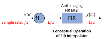
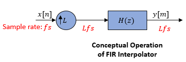
Conceptually, the FIR interpolator (as shown in the schematic) consists of an upsampler followed by an FIR anti-imaging filter, which is usually an approximation of an ideal band-limited interpolation filter. To design an FIR anti-imaging filter, use the designMultirateFIR function. The upsampler upsamples each channel of the input to a higher rate by inserting L–1 zeros between samples. The FIR filter that follows filters each channel of the upsampled data. The resulting discrete-time signal has a sample rate that is L times the original sample rate.

FIR interpolator contains an upsampler followed by an anti-imaging FIR filter.

However, the actual block algorithm implements a direct-form FIR polyphase structure, an efficient equivalent of the combined system depicted in the diagram. For more details, see Algorithms.

The block supports C and C++ code generation.

Examples

expand all

Interpolate a sinusoidal signal whose frame size varies during simulation. The Variable FIR Interpolation block determines the frame size of the interpolated output based on the value of the Specification parameter.

Specify Interpolation Factor

Open and inspect the SpecifyInterpolationFactor.slx model. The Specification parameter in the Variable FIR Interpolation block dialog box is set to Interpolation factor. In this mode, you specify the interpolation factor in the block dialog box or through an input port. During simulation, when the input frame size varies, the block maintains this interpolation factor and varies the output frame size so that output frame size equals input frame size x interpolation factor.

The Variable FIR Interpolation block outputs a variable-size signal.

Specify Output Frame Length

Open and inspect the SpecifyOutFrameLength.slx model. The Specification parameter in the Variable FIR Interpolation block dialog box is set to Output frame length. In this mode, you specify the output frame length in the block dialog box. During simulation, when the input frame size varies, the block varies the interpolation factor in order to maintain the frame length of the output signal. The output frame size equals input frame size x interpolation factor.

The Variable FIR Interpolation block outputs a fixed-size signal.

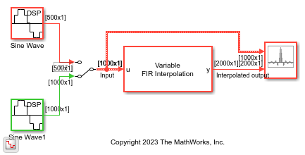
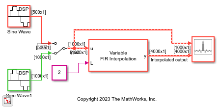
Interpolate a sinusoidal signal by varying the interpolation factor using the Variable FIR Interpolation block. You can vary the interpolation factor in the block dialog box or through an input port while the simulation is running.

Open the model. The input is a sinusoidal signal with a frequency of 500 Hz, sample time of 1/44100 s, and contains 100 samples per frame. Pass this signal through the Variable FIR Interpolation block. The Maximum interpolation factor parameter in the block is 24. The interpolation factor that you input through the port is 4.

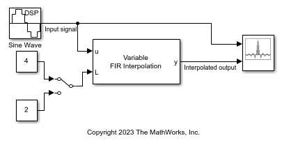
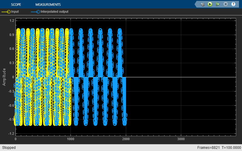
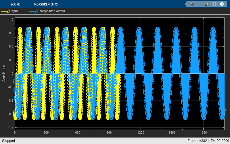
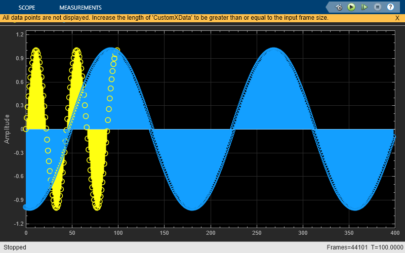
Run the model. The Array Plot block shows the input signal and the interpolated output on the display.

While the simulation is running, change the interpolation factor to 2 by clicking the Manual Switch. The span of the interpolated output updates in the Array Plot display. You can change the interpolation factor to any value that is an integer factor of the maximum interpolation factor of 24.

If you specify the interpolation factor in the block dialog box, you can tune the Interpolation factor parameter in the block dialog box while the simulation is running and the block updates the interpolated output accordingly.

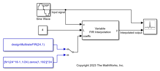
Interpolate a sinusoidal signal using the Variable FIR Interpolation block. You can vary the filter coefficients in the block dialog box or through an input port while the simulation is running.

Open the model. The input is a sinusoidal signal with a frequency of 500 Hz, sample time of 1/44100 s, and contains 100 samples per frame. Pass this signal through the Variable FIR Interpolation block. The Maximum interpolation factor parameter in the Variable FIR Interpolation block is set to 24. Specify the interpolation factor and the filter coefficients through the L and the coeffs ports, respectively. The interpolation factor is 4 and the filter coefficients are generated using the designMultirateFIR(24,1) function. This function generates an effective anti-imaging lowpass filter with a normalized cutoff frequency no greater than 1/24.

You can vary the filter coefficients using the Manual Switch.

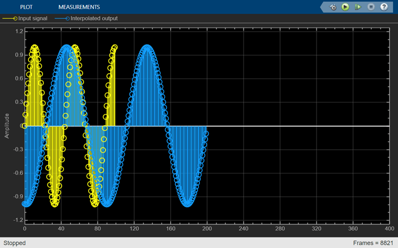
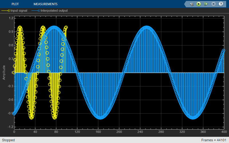
Run the model. The Array Plot block shows the input signal and the interpolated output in the display.

While the simulation is running, change the filter coefficients by clicking the Manual Switch. On the second branch, the fir1 function generates the coefficients of a lowpass filter that has a similar passband frequency response and the same number of coefficients as the first filter. Note that you cannot change the number of filter coefficients while the simulation is running.

Ports

Input

expand all

Specify the data input as a vector or a matrix of size P-by-Q. The block treats each column of the input signal as a separate channel. If the input is a two-dimensional signal, the first dimension represents the channel length (or frame size) and the second dimension represents the number of channels. If the input is a one-dimensional signal, then the block interprets it as a single channel.

The block accepts variable-size input signals, that is, you can change the size of each input channel during simulation, but you cannot change the number of channels.

Data Types: single | double
Complex Number Support: Yes

Specify the interpolation factor L as a positive integer that is an integer factor of the maximum interpolation factor. For example, if you set Maximum interpolation factor to 24, then the possible values for interpolation factor are 1, 2, 3, 4, 6, 8, 12, and 24.

You can tune the interpolation factor while the simulation is running. For an example, see Interpolate Sinusoidal Signal with Tunable Interpolation Factor.

Dependencies

To enable this port:

  • Set Specification to Interpolation factor. (since R2023b)

  • Select the Specify interpolation factor from input port parameter.

Data Types: single | double | int8 | int16 | int32 | int64 | uint8 | uint16 | uint32 | uint64

Specify the numerator coefficients of the FIR filter transfer function H(z).

H(z)=b0+b1z1+...+bNzN

You can generate the FIR filter coefficient vector, b = [b0, b1, …, bN], using one of the DSP System Toolbox™ filter design functions such as designMultirateFIR, firnyquist, firgr or firceqrip.

Compute the filter coefficients based on the maximum interpolation factor Lmax instead of the interpolation factor L. For example, if Lmax is 24 and L is 8, and you used designMultirateFIR as the design function, compute the filter coefficients using designMultirateFIR(24,1) instead of designMultirateFIR(8,1).

To act as an effective anti-imaging filter, the coefficients usually correspond to a lowpass filter with a normalized cutoff frequency no greater than the reciprocal of the maximum interpolation factor. To design such a filter, use the designMultirateFIR function.

The block internally initializes all filter states to zero.

You can change the filter coefficients during simulation but the number of filter coefficients must remain constant. For an example, see Specify Filter Coefficients Through Input Port.

Dependencies

To enable this port, set the Coefficient source parameter to Input port.

Data Types: single | double
Complex Number Support: Yes

Output

expand all

Interpolated output, returned as a vector or a matrix.

When you set the Specification parameter to Interpolation factor (since R2023b), the size of the output signal is Lmax × P-by-Q, where P is the input frame size, Q is the number of input channels, and Lmax is the maximum interpolation factor. However, the block computes only L × P-by-Q samples. The remaining samples in the output signal are zero.

If the input is a variable-size signal, the block outputs a variable-size signal so as to maintain the interpolation factor.

When you set the Specification parameter to Output frame length, the size of the output signal is Po-by-Q, where Po is the value you specify in the Output frame length parameter. (since R2023b)

If the input is a variable-size signal, the block varies the interpolation factor accordingly and outputs a fixed-size signal. (since R2023b)

The complexity of the output signal depends on the complexity of the input signal and the complexity of the filter coefficients. See this table for more details.

Input SignalFilter CoefficientsOutput Signal
RealComplexComplex
RealRealReal
ComplexComplexComplex
ComplexRealComplex

Data Types: single | double
Complex Number Support: Yes

Parameters

expand all

Since R2023b

Specify the mode in which you control the interpolation factor.

When you set Specification to:

  • Interpolation factor –– The block maintains the interpolation factor that you specify. If the input signal frame length changes during simulation (variable-size input signal), the output frame length changes in a way as to maintain the interpolation factor L.

    A variable-size input generates a variable-size output.

  • Output frame length –– The block maintains the output frame length that you specify. If the input signal frame length changes during simulation (variable-size input signal), the interpolation factor changes in a way as to maintain the output frame length Po.

    A variable-size input generates a fixed-size output.

Specify the maximum interpolation factor Lmax as a positive integer. The interpolation factor you specify through the input port L must be a factor of the value you specify in this parameter.

When you set the Specification parameter to Output frame length, the block treats the output frame length as the maximum interpolation factor Lmax. (since R2023b)

Dependencies

To enable this port, set the Specification parameter to Interpolation factor. (since R2023b)

When you select this parameter, you can specify the interpolation factor through the input port L. When you clear this parameter, you can specify the interpolation factor in the block dialog box through the Interpolation factor parameter.

Dependencies

To enable this parameter, set the Specification parameter to Interpolation factor. (since R2023b)

Specify the interpolation factor L as a positive integer that is an integer factor of the maximum interpolation factor. For example, if you set Maximum interpolation factor to 24, then the possible values for Interpolation factor are 1, 2, 3, 4, 6, 8, 12, and 24.

You can tune the interpolation factor while the simulation is running.

When you set the Specification parameter to Output frame length, the block treats the ratio of the output frame length Po to the input frame length P as the interpolation factor L, that is, L = Po/P. (since R2023b)

Tunable: Yes

Dependencies

To enable this parameter:

  • Set the Specification parameter to Interpolation factor. (since R2023b)

  • Clear the Specify interpolation factor from input port parameter.

Since R2023b

Specify the output frame length Po as a positive integer. In this mode, the block maintains the frame length of the output signal at the value you specify in this parameter. If the input signal frame length changes during simulation (variable-size input signal), the interpolation factor of the block changes in a way as to maintain the output frame length.

The input frame length must be a divisor of the output frame length.

The value you specify in this parameter determines the maximum interpolation factor Lmax and the current interpolation factor L. For more details, see the Maximum interpolation factor and the Interpolation factor parameters.

Dependencies

To enable this parameter, set the Specification parameter to Output frame length.

Specify the FIR filter coefficient source as one of the following:

  • Auto –– The block designs an FIR interpolator using the interpolation factor in the Interpolation factor parameter. The designMultirateFIR function designs the filter and returns the coefficients used by the block.

    For more information on the filter design, see Orfanidis [1].

  • Dialog parameter –– Specify the filter coefficients through the Prototype filter coefficients parameter in the block dialog box.

  • Input port –– Specify the filter coefficients through the coeffs input port.

Specify the numerator coefficients of the FIR filter transfer function H(z).

H(z)=b0+b1z1+...+bNzN

You can generate the FIR filter coefficient vector, b = [b0, b1, …, bN], using one of the DSP System Toolbox filter design functions such as designMultirateFIR, firnyquist, firgr or firceqrip.

Compute the filter coefficients based on the maximum interpolation factor Lmax instead of the interpolation factor L. For example, if Lmax is 24 and L is 8, and you used designMultirateFIR as the design function, compute the filter coefficients using designMultirateFIR(24,1) instead of designMultirateFIR(8,1).

To act as an effective anti-imaging filter, the coefficients usually correspond to a lowpass filter with a normalized cutoff frequency no greater than the reciprocal of the maximum interpolation factor. To design such a filter, use the designMultirateFIR function.

The block internally initializes all filter states to zero.

You can change the filter coefficients during simulation but the number of filter coefficients must remain constant.

Tunable: Yes

Dependencies

To enable this parameter, set the Coefficient source parameter to Dialog parameter.

Click this button to open the filter visualizer and display the magnitude response of the variable FIR interpolation filter. The response is based on the parameters you select in the block dialog box. To update the magnitude response while the filter visualizer is running, modify the parameters in the dialog box and click Apply.

You can configure the plot settings and the signal measurements from the interface of the visualizer.

On the Scope tab, the Configuration section allows you to modify the plot settings. Click Magnitude Phase to display the magnitude and phase response of the filter. On the Measurements tab, you can measure the signal statistics, place data cursors, and display the peak values of the selected signal.

For more details on the filter visualizer interface and its tools, see Configure Filter Visualizer.

Dependencies

You cannot view the filter response when you set the Specification parameter to Output frame length (since R2023b) or the Coefficient source parameter to Input port. To view the filter response, set the Specification parameter to Interpolation factor (since R2023b) and the Coefficient source parameter to Auto or Dialog parameter.

Specify the type of simulation to run. You can set this parameter to:

  • Interpreted execution –– Simulate model using the MATLAB® interpreter. This option shortens startup time.

  • Code generation –– Simulate model using generated C code. The first time you run a simulation, Simulink® generates C code for the block. The C code is reused for subsequent simulations as long as the model does not change. This option requires additional startup time but provides faster subsequent simulations.

Block Characteristics

Data Types

double | single

Direct Feedthrough

no

Multidimensional Signals

no

Variable-Size Signals

yes

Zero-Crossing Detection

no

Algorithms

The FIR interpolation filter is implemented efficiently using a polyphase structure.

To derive the polyphase structure, start with the transfer function of the FIR filter:

H(z)=b0+b1z1+...+bNzN

N+1 is the length of the FIR filter.

You can rearrange this equation as follows:

H(z)=(b0+bLmaxzLmax+b2Lmaxz2Lmax+...+bNLmax+1z(NLmax+1))+z1(b1+bLmax+1zLmax+b2Lmax+1z2Lmax+...+bNLmax+2z(NLmax+1))+z(Lmax1)(bLmax1+b2Lmax1zLmax+b3Lmax1z2Lmax+...+bNz(NLmax+1))

Lmax is the number of polyphase components, and its value equals the maximum interpolation factor.

You can write H(z) as:

H(z)=E0(zLmax)+z1E1(zLmax)+...+z(Lmax1)E(Lmax1)(zLmax)

E0(zLmax), E1(zLmax), ..., ELmax-1(zLmax) are polyphase components of the FIR filter H(z).

During simulation, the algorithm reconstructs the filter H(z) based on the current interpolation factor L.

Rewriting H(z) in terms of the interpolation factor L.

H(z)=E0(zL)+z1Er(zL)+...+z(L1)E(L1)r(zL)

where, r = Lmax/L.

Conceptually, the FIR interpolation filter contains an upsampler followed by an FIR lowpass filter H(z).

FIR interpolator contains an upsampler followed by an anti-imaging FIR filter.

Replace H(z) with its polyphase representation.
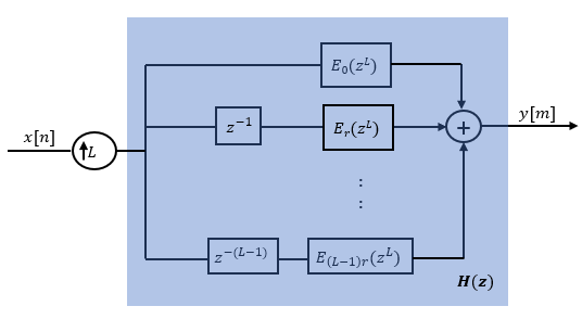
Here is the multirate noble identity for interpolation.

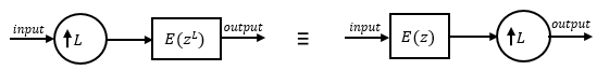
Applying the noble identity for interpolation moves the upsampling operation to after the filtering operation. This move enables you to filter the signal at a lower rate.

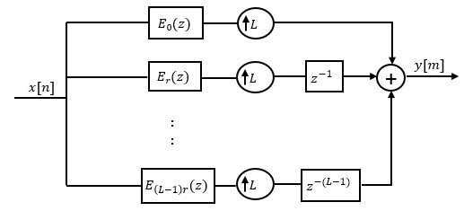
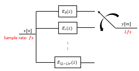
You can replace the upsampling operator, delay block, and adder with a commutator switch. The switch starts on the first branch 0 and moves in the counterclockwise direction, each time receiving one sample from each branch. The interpolator effectively outputs L samples for every one input sample it receives. Hence the sample rate at the output of the FIR interpolation filter is Lfs.

References

[1] Orfanidis, Sophocles J. Introduction to Signal Processing. Upper Saddle River, NJ: Prentice-Hall, 1996.

Extended Capabilities

C/C++ Code Generation
Generate C and C++ code using Simulink® Coder™.

Version History

Introduced in R2023a

expand all