CIC Compensation Decimator
Compensate for CIC filter using FIR decimator
Libraries:
DSP System Toolbox /
Filtering /
Multirate Filters
Description
The CIC Compensation Decimator block uses an FIR polyphase decimator as the compensation filter. CIC compensation decimators are multirate FIR filters that you cascade with CIC decimators to mitigate the drawbacks of the CIC filters.
CIC decimation filters are used in areas that require high decimation. These filters are popular in ASICs and FPGAs, since they do not have any multipliers. CIC filters have two drawbacks:
CIC filters have a magnitude response that causes a droop in the passband region. This magnitude response is:
M — Differential delay
n — Number of stages
ω — Normalized angular frequency
CIC filters have a wide transition region.
The compensation decimator filters have an inverse passband response to correct for the CIC droop, and they have a narrow transition width.
This block brings the capabilities of the dsp.CICCompensationDecimator
System object™ to the Simulink® environment.
Ports
Input
Output
Parameters
Main Tab
Specify the rate-change factor of the CIC filter as a positive integer. The block compensates the CIC filter using an FIR polyphase decimator as the compensation filter.
Specify the number of decimator and comb sections in the CIC filter as a positive integer. The block compensates the CIC filter using an FIR polyphase decimator as the compensation filter.
Specify the delay value used in each comb section of the CIC filter as a positive integer. The block compensates the CIC filter using an FIR polyphase decimator as the compensation filter.
Specify the decimation factor M of the compensation filter as a positive integer. The number of input rows must be a multiple of the decimation factor.
When you select this check box, the block designs filter with the minimum order that meets the passband frequency, stopband frequency, passband ripple, and stopband attenuation specifications. When you clear this check box, the block designs filter with the order that you specify in the Filter order parameter.
By default, this check box is selected.
Specify the order of the compensation filter as a positive integer.
Dependency
To enable this parameter, clear the Minimum order filter design parameter.
Specify the passband edge frequency of the compensation filter as a positive scalar in Hz or in normalized frequency units (since R2024a).
If you set the Sample rate mode parameter to:
Specify on dialogorInherit from input port— The value of the passband edge frequency is in Hz and must be in the range Fpass < Fstop < Fs/2, where Fstop is the stopband edge frequency and Fs is the input sample rate that you specify through the Input sample rate (Hz) parameter.Use normalized frequency (0 to 1)— The value of the passband edge frequency is in normalized frequency units and must be in the range Fpass < Fstop <1.0.
(since R2024a)
Specify the stopband edge frequency of the compensation filter as a positive scalar in Hz or in normalized frequency units (since R2024a).
If you set the Sample rate mode parameter to:
Specify on dialogorInherit from input port— The value of the stopband edge frequency is in Hz and must be in the range Fpass < Fstop < Fs/2, where Fpass is the passband edge frequency and Fs is the input sample rate that you specify through the Input sample rate (Hz) parameter.Use normalized frequency (0 to 1)— The value of the stopband edge frequency is in normalized frequency units and must be in the range Fpass < Fstop <1.0.
(since R2024a)
Dependency
To enable this parameter, select the Minimum order filter design parameter.
Specify the passband ripple of the compensation filter as a positive real scalar in dB.
Specify the stopband attenuation of the compensation filter as a positive real scalar in dB.
Since R2024a
Specify the input sample rate using one of these options:
Use normalized frequency (0 to
											1)
— Specify the passband edge and the stopband edge frequencies in normalized frequency units (0 to 1).Specify on dialog— Specify the input sample rate in the block dialog box using the Input sample rate (Hz) parameter.Inherit from input port— The block inherits the sample rate from the input signal.
Specify the sample rate of the input signal as a positive real scalar in Hz.
Dependencies
To enable this parameter,
set the Sample rate mode parameter to
Specify on dialog. (since R2024a)
Since R2023a
Specify whether fixed-size input signals (whose size does not change during simulation) can have an arbitrary frame length, where the frame length does not have to be a multiple of the decimation factor. The block uses this parameter setting only for fixed-size input signals and ignores this parameter if the input has a variable-size.
When the input signal is a variable-size signal, the signal can have arbitrary frame length, that is, the frame length does not have to be a multiple of the decimation factor.
For fixed-size input signals, if you:
Select the Allow arbitrary frame length for fixed-size input signals parameter, the frame length of the signal does not have to be a multiple of the decimation factor. If the input is not a multiple of the decimation factor, then the output is generally a variable-size signal. Therefore, to support arbitrary input size, the block must also support variable-size operations, which you can enable by selecting the Allow arbitrary frame length for fixed-size input signals parameter.
Clear the Allow arbitrary frame length for fixed-size input signals parameter, the input frame length must be a multiple of the decimation factor.
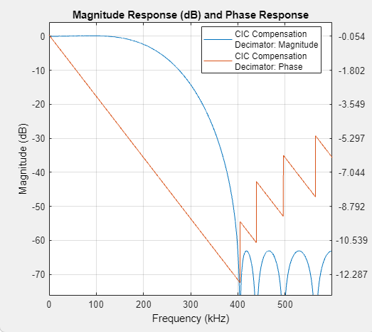
Click this button to open the Filter Visualization Tool FVTool and display the magnitude and phase response of the CIC Compensation Decimator. The response is based on the values you specify in the block parameters dialog box. Changes made to these parameters update FVTool.
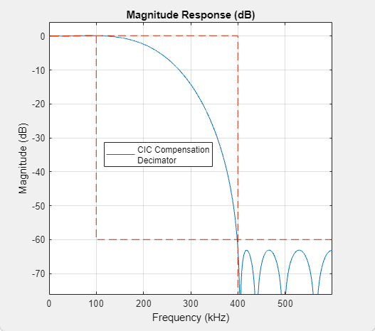
To view the magnitude response and phase response simultaneously, click the Magnitude and Phase responses button on the toolbar.
Specify the type of simulation to run. You can set this parameter to:
Interpreted execution— Simulate model using the MATLAB® interpreter. This option shortens startup time.Code generation— Simulate model using generated C code. The first time you run a simulation, Simulink generates C code for the block. The C code is reused for subsequent simulations as long as the model does not change. This option requires additional startup time but provides faster subsequent simulations.
Data Types Tab
Select the rounding
mode for fixed-point operations. The default is
Floor.
Specify the fixed-point data type of the coefficients as one of the following:
fixdt(1,16)(default) — Signed fixed-point data type of word length16with binary point scaling. The block determines the fraction length automatically from the coefficient values in such a way that the coefficients occupy maximum representable range without overflowing.fixdt(1,16,0)— Signed fixed-point data type of word length16and fraction length0. You can change the fraction length to any other integer value.<data type expression>— Specify the coefficients data type by using an expression that evaluates to a data type object. For example,numerictype(fixdt([ ],16,15)). Specify the sign mode of this data type as[ ]or true.Refresh Data Type— Refresh to the default data type.
Click the Show data type assistant
button ![]() to display the data type assistant,
which helps you set the coefficients data type.
to display the data type assistant,
which helps you set the coefficients data type.
See Specify Data Types Using Data Type Assistant (Simulink) for more information.
Block Characteristics
Data Types |
|
Direct Feedthrough |
|
Multidimensional Signals |
|
Variable-Size Signals |
|
Zero-Crossing Detection |
|
Algorithms
The response of a CIC filter is given by:
R, D, and N are the rate change factor, the differential delay, and the number of sections in the CIC filter, respectively.
After decimation, the CIC response has the form:
The normalized version of this last response is the one that the CIC compensator needs to compensate. Hence, the passband response of the CIC compensator should take the following form:
where ωp is the passband frequency of the CIC compensation filter.
Notice that when ω/2R ≪ π, the previous equation for Hciccomp(ω) can be simplified using the fact that sin(x) ≅ x:
This previous equation is the inverse sinc approximation to the true inverse passband response of the CIC filter.