dsp.FIRFilter
Static or time-varying FIR filter
Description
The dsp.FIRFilter
System object™ filters each channel of the input using static or time-varying FIR filter
implementations.
To filter each channel of the input:
Create the
dsp.FIRFilterobject and set its properties.Call the object with arguments, as if it were a function.
To learn more about how System objects work, see What Are System Objects?
This object supports C/C++ code generation and SIMD code generation under certain conditions. For more information, see Code Generation.
Creation
Syntax
Description
fir = dsp.FIRFilterfir, which independently filters each
channel of the input over time using a specified FIR filter implementation.
fir = dsp.FIRFilter(num)fir, with the Numerator property
set to num.
fir = dsp.FIRFilter(___,SampleRate=Value)"normalized". (since R2026a)
To specify an input sample rate of 22050 Hz, set
SampleRate to 22050. To specify the input sample rate in normalized
units, set SampleRate to "normalized". (since R2026a)
fir = dsp.FIRFilter(___,PropertyName=Value)InitialConditions to
3.
Properties
Usage
Description
Input Arguments
Output Arguments
Object Functions
To use an object function, specify the
System object as the first input argument. For
example, to release system resources of a System object named obj, use
this syntax:
release(obj)
Examples
Use an FIR filter to apply a lowpass filter to a waveform with two sinusoidal components.
 t = (0:1000)'/8e3;
 xin = sin(2*pi*0.3e3*t)+sin(2*pi*3e3*t);

 sr = dsp.SignalSource;
 sr.Signal = xin;
 sink = dsp.SignalSink;

 fir = dsp.FIRFilter(designLowpassFIR(FilterOrder=10,CutoffFrequency=0.5));

sa = spectrumAnalyzer(...
     SampleRate=8e3,...
     Method="welch",...
     PlotAsTwoSidedSpectrum=false,...
     OverlapPercent=80,...
     SpectrumUnits="dBW",...
     YLimits=[-150 -10]);

 while ~isDone(sr)
      input = sr();
      filteredOutput = fir(input);
      sink(filteredOutput);
      sa(filteredOutput)
 end

 filteredResult = sink.Buffer;
 filterAnalyzer(fir,SampleRates=8000)

Design an FIR filter as a System object.
N = 10;
Fc = 0.4;
firFiltObj = designLowpassFIR(FilterOrder=N,CutoffFrequency=Fc,SystemObject=true)
firFiltObj =
  dsp.FIRFilter with properties:

            Structure: 'Direct form'
      NumeratorSource: 'Property'
            Numerator: [-1.2414e-18 -0.0126 -0.0247 0.0635 0.2748 0.3981 0.2748 0.0635 -0.0247 -0.0126 -1.2414e-18]
    InitialConditions: 0

  Show all properties
filterAnalyzer(firFiltObj)

Create a dsp.FIRFilter object, and set the NumeratorSource property to "Input port" so that you can vary the coefficients of the FIR filter through the input port during simulation.
firFilt = dsp.FIRFilter(NumeratorSource="Input port")firFilt =
dsp.FIRFilter with properties:
Structure: 'Direct form'
NumeratorSource: 'Input port'
InitialConditions: 0
Show all properties
Create a spectrumAnalyzer object to visualize the spectra of the input and output signals.
spectrumScope = spectrumAnalyzer(SampleRate=44100,PlotAsTwoSidedSpectrum=false,...
    ChannelNames=["Input Signal","Filtered Signal"]);
Create a dsp.DynamicFilterVisualizer object to visualize the magnitude response of the varying filter.
filterViz = dsp.DynamicFilterVisualizer(NormalizedFrequency=true);
Stream in random data and filter the signal using the dsp.FIRFilter object. Use the designLowpassFIR function to design the filter coefficients. By default, this function returns a vector of FIR filter coefficients. Assign these coefficients to the dsp.FIRFilter object.
Vary the cutoff frequency of the filter during simulation. The designLowpassFIR function redesigns the coefficients based on the updated filter specifications. Pass these updated coefficients to the FIR filter. Visualize the spectra of the input and filtered signals using the spectrum analyzer.
Fcut = 0.5;
for idx = 1:500
    num = designLowpassFIR(FilterOrder=30,CutoffFrequency=Fcut,Window="hann");
    x = randn(1024,1);
    y = firFilt(x,num);
    spectrumScope(x,y);
    filterViz(num,1);
    Fcut = Fcut + 0.0005;
end


Design and implement a lowpass FIR filter object using the designLowpassFIR function. The function returns a dsp.FIRFilter object when you set the SystemObject argument to true. To design the filter in single-precision, use the Datatype or like argument. Alternatively, you can specify any of the numerical arguments in single-precision.
firFilt = designLowpassFIR(FilterOrder=30,CutoffFrequency=0.5,Window="hann",...
        Datatype="single",SystemObject=true)
firFilt =
  dsp.FIRFilter with properties:

            Structure: 'Direct form'
      NumeratorSource: 'Property'
            Numerator: [0 2.1297e-19 0.0011 -1.8613e-18 -0.0048 4.8729e-18 0.0122 -8.7270e-18 -0.0251 1.2757e-17 0.0477 -1.6267e-17 -0.0960 1.8649e-17 0.3148 0.5000 0.3148 1.8649e-17 -0.0960 -1.6267e-17 0.0477 1.2757e-17 -0.0251 … ] (1×31 single)
    InitialConditions: 0

  Show all properties
Set the input sample rate to 44.1 kHz using the setInputSampleRate function.
setInputSampleRate(firFilt,44100)
Create a dsp.DynamicFilterVisualizer object to visualize the magnitude response of the filter.
filterViz = dsp.DynamicFilterVisualizer;
filterViz(firFilt)

Create a spectrumAnalyzer object to visualize the spectra of the input and output signals.
spectrumScope = spectrumAnalyzer(SampleRate=44100,PlotAsTwoSidedSpectrum=false,...
    ChannelNames=["Input Signal","Filtered Signal"]);
Stream in random data and filter the signal using the dsp.FIRFilter object. Visualize the spectra of the input and filtered signals using the spectrum analyzer.
for idx = 1:500
    x = randn(1024,1);
    y = firFilt(x);
    spectrumScope(x,y);
end

Design an equiripple FIR halfband filter with the order of 24 and a transition width of 0.1 using the designHalfbandFIR function. Assign the filter coefficients to a dsp.FIRFilter System object.
b = designHalfbandFIR(FilterOrder=24,DesignMethod="equiripple");
hbFIR = dsp.FIRFilter(b);
Create a dsp.DynamicFilterVisualizer object and visualize the magnitude response of the filter.
dfv = dsp.DynamicFilterVisualizer(NormalizedFrequency=true);
dfv(hbFIR);

Create a spectrumAnalyzer object to visualize the spectra of the input and output signals.
scope = spectrumAnalyzer(SampleRate=2, PlotAsTwoSidedSpectrum=false,...
    ChannelNames=["Input Signal","Filtered Signal"]);
Stream in random data and filter the signal using the FIR halfband filter.
for i = 1:1000
    x = randn(1024, 1);
    y = hbFIR(x);
    scope(x,y);
end

Since R2023b
Design a lowpass FIR filter using the designfilt function.
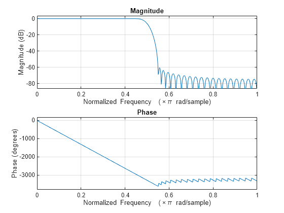
The filter is a minimum order filter with a passband frequency of 0.45 and a stopband frequency of 0.55 in normalized frequency units. The passband ripple is 1 dB and the stopband attenuation is 60 dB. Use the Kaiser window design method and set the SystemObject argument to true.
With these specifications, the designfilt function generates a dsp.FIRFilter System object™.
lpFIRFilter = designfilt("lowpassfir", ...
    PassbandFrequency=0.45,StopbandFrequency=0.55, ...
    PassbandRipple=1,StopbandAttenuation=60, ...
    DesignMethod="kaiserwin",SystemObject=true)
lpFIRFilter =
  dsp.FIRFilter with properties:

            Structure: 'Direct form'
      NumeratorSource: 'Property'
            Numerator: [1.2573e-04 -1.9141e-04 -2.7282e-04 3.7207e-04 4.9141e-04 -6.3325e-04 -8.0016e-04 9.9490e-04 0.0012 -0.0015 -0.0018 0.0021 0.0025 -0.0029 -0.0034 0.0040 0.0046 -0.0053 -0.0060 0.0069 0.0079 -0.0090 -0.0102 0.0116 … ] (1×74 double)
    InitialConditions: 0

  Show all properties
Visualize the magnitude and phase responses of this filter using freqz.
freqz(lpFIRFilter.Numerator)
Since R2026a
Using SampleRate Argument
Specify the input sample rate explicitly while constructing the dsp.FIRFilter object using the SampleRate argument.
firFilt = dsp.FIRFilter(SampleRate=22050)
firFilt =
  dsp.FIRFilter with properties:

            Structure: 'Direct form'
      NumeratorSource: 'Property'
            Numerator: [0.5000 0.5000]
    InitialConditions: 0

  Show all properties
You can view this information using the Input sample rate field of the info function.
info(firFilt)
ans = 7×35 char array
    'Discrete-Time FIR Filter (real)    '
    '-------------------------------    '
    'Filter Structure  : Direct-Form FIR'
    'Filter Length     : 2              '
    'Stable            : Yes            '
    'Linear Phase      : Yes (Type 2)   '
    'Input sample rate : 22050          '
Visualize the frequency response of the filter using filterAnalyzer. Note the frequency range from 0 to 11025 Hz.
filterAnalyzer(firFilt,FilterNames="FIRFilter22050Hz")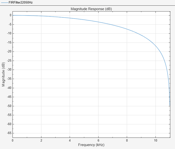
Using setInputSampleRate Function
To specify the input sample rate after constructing the object, use the setInputSampleRate function.
setInputSampleRate(firFilt,44100)
To confirm, view the sample rate information using the info function.
info(firFilt)
ans = 7×35 char array
    'Discrete-Time FIR Filter (real)    '
    '-------------------------------    '
    'Filter Structure  : Direct-Form FIR'
    'Filter Length     : 2              '
    'Stable            : Yes            '
    'Linear Phase      : Yes (Type 2)   '
    'Input sample rate : 44100          '
Visualize the frequency response of the filter using filterAnalyzer. Note the change in frequency interval from 0 to 22050 Hz.
filterAnalyzer(firFilt,FilterNames="FIRFilter44100Hz")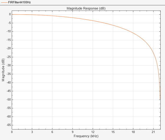
Algorithms
This object implements the algorithm, inputs, and outputs described on the Discrete FIR Filter (Simulink) block reference page. The object properties correspond to the block parameters.
Extended Capabilities
Version History
Introduced in R2012aSee Also
Functions
freqz|filterAnalyzer|impz|info|coeffs|cost|grpdelay|outputDelay|designLowpassFIR|designBandpassFIR|designBandstopFIR|designHighpassFIR|designFracDelayFIR|designHalfbandFIR|setInputSampleRate
Objects
Blocks
- Discrete FIR Filter (Simulink)