Reglerentwurf
Zum Entwickeln und Analysieren von in der Simulink-Umgebung modellierten Regelungssystemen empfiehlt sich die Software Simulink Control Design.
Simulink Control Design erweitert Simulink und ermöglicht es Ihnen, Betriebspunkte zu finden und exakte Linearisierungen von Simulink-Modellen bei verschiedenen Betriebsbedingungen zu berechnen. Simulink Control Design bietet zudem Tools, mit denen Sie simulationsbasierte Frequenzgänge berechnen können, ohne Ihr Modell zu verändern.
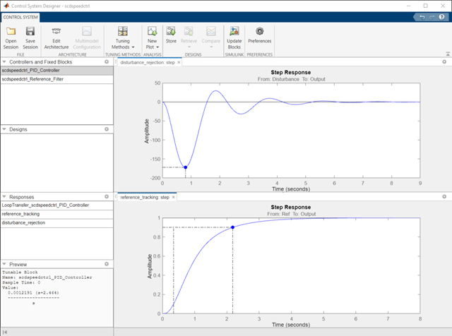
Simulink Control Design bietet mehrere Ansätze zur Anpassung von Simulink-Blöcken, wie z. B. Transferfunktion und PID-Controller-Blöcke. Mithilfe dieser Verfahren und Tools können Sie:
Rückkopplungsschleifen, die die Blöcke PID-Controller oder PID-Controller (2DOF) enthalten, automatisch anpassen.
SISO-Rückkopplungsschleifen mit allen anpassbaren Simulink-Blöcken grafisch oder automatisch abstimmen.
Simulink-Modelle von Regelungssystemen mit beliebiger Struktur anpassen, um übergeordnete Entwurfsziele wie Referenzverfolgung, Störungsunterdrückung und Stabilitätsmargen zu erfüllen.
Themen
Trimming und Linearisierung
- Compute Steady-State Operating Points (Simulink Control Design)
To obtain a steady-state operating point, you can trim your model using numerical optimization techniques or simulate your model until it reaches a steady-state condition. - Linearize Nonlinear Models (Simulink Control Design)
Obtain a linear approximation of a nonlinear system that is valid in a small region around an operating point. - Choose Linearization Tools (Simulink Control Design)
Simulink Control Design software lets you perform linear analysis of nonlinear models using a user interface, functions, or blocks. - Linearize Simulink Model at Model Operating Point (Simulink Control Design)
Linearize a model at its operating point consisting of initial state values and input signals. - Linearize at Trimmed Operating Point (Simulink Control Design)
You can linearize a Simulink model at an operating point that meets specified input, output, or state constraints.
Schätzung des Frequenzgangs
- Frequency Response Estimation Basics (Simulink Control Design)
A frequency response describes the steady-state response of a system to sinusoidal inputs. Simulink Control Design lets you estimate the frequency response of a model or perform online estimation of a physical plant. - Estimate Frequency Response Using Model Linearizer (Simulink Control Design)
Estimate the frequency response of a Simulink model using a manually constructed sinestream input signal.
PID-Reglerentwurf
- Introduction to Model-Based PID Tuning in Simulink (Simulink Control Design)
Use PID Tuner for interactive tuning of PID gains in a Simulink model containing a PID Controller or PID Controller (2DOF) block. - PID Autotuning for a Plant Modeled in Simulink (Simulink Control Design)
Use the PID autotuning algorithm to tune against a plant modeled in Simulink while the model is running.
Anpassung von Reglerentwürfen
- Tune Control Systems in Simulink (Simulink Control Design)
At the command line, usesystuneorlooptuneto automatically tune control systems modeled in Simulink.
Adaptiver Reglerentwurf
- Extremum Seeking Control (Simulink Control Design)
Update controller parameters to maximize an objective function in the presence of unknown system dynamics. - Model Reference Adaptive Control (Simulink Control Design)
Compute control actions to make an uncertain controlled system track the behavior of a given reference plant model.
Reglerentwurf-Anwendung
- Thermal Modeling and Control Design for CPU Chip Cooling System (Control System Toolbox)
Create a CPU and heat sink thermal model, perform model order reduction, and design a controller for a cooling system.
- Create Heat Sink Finite Element Model and Export Data for State-Space Simulation (Control System Toolbox)
- Import Finite Element Model Data to Simulink (Control System Toolbox)
- Create Low-Order LPV Model of CPU and Heat Sink Model (Control System Toolbox)
- Tune PI Controller for Heat Sink Model (Control System Toolbox)


