fdesign.bandstop
Bandstop filter design specification object
Syntax
Description
The fdesign.bandstop function returns a
bandstop filter design specification object that contains the
specifications for a filter, such as passband frequency, stopband frequency, passband
ripple, and filter order. Then, use the design function to design the filter from the filter design
specifications object.
For more control options, see Filter Design Procedure. For a complete workflow, see Design a Filter in Fdesign — Process Overview.
bandstopSpecs = fdesign.bandstop
First passband frequency set to 0.35.
First stopband frequency set to 0.45.
Second stopband frequency set to 0.55.
Second passband frequency set to 0.65.
First passband ripple 1 dB.
Stopband attenuation set to 60 dB.
Second passband ripple set to 1 dB.
bandstopSpecs = fdesign.bandstop(spec,value1,...,valueN)spec. After the expression, specify a value for each option. If
you do not specify values after the spec argument, the function
assumes the default values.
bandstopSpecs = fdesign.bandstop(___,Fs)Fs must be specified as a scalar trailing the other
numerical values provided. In this case, all frequencies in the specifications are
in Hz as well.
The design specification
fdesign.bandstop('Fp1,Fst1,Fst2,Fp2,Ap1,Ast,Ap2',.4,.5,.6,.7,1,80,.5)
designs the same filter as
fdesign.bandstop('Fp1,Fst1,Fst2,Fp2,Ap1,Ast,Ap2',1600,2000,2400,2800,1,80,0.5,8000)
bandstopSpecs = fdesign.bandstop(___,magunits)magunits can be one of the following:
'linear', 'dB', or
'squared'. If this argument is omitted,
'dB' is assumed. The magnitude specifications are always
converted and stored in dB regardless of how they were specified. If
Fs is provided, magunits must follow
Fs in the input argument list.
Examples
Design a constrained-band FIR equiripple filter of order 60 with a stopband of [12.8 22.4] kHz. Both passband ripple values are constrained to 1 dB. The sample rate is 64 kHz.
Create a bandstop filter design specification object using the fdesign.bandstop function and specify these design parameters.
bandstopSpecs = fdesign.bandstop('N,Fp1,Fst1,Fst2,Fp2,C',60,9.6e3,12.8e3,22.4e3,25.6e3,64000);Constrain the two passbands with a passband ripple of 1 dB.
bandstopSpecs.Passband1Constrained = true;
bandstopSpecs.Apass1 = 1;
bandstopSpecs.Passband2Constrained = true;
bandstopSpecs.Apass2 = 1;
Design the bandstop filter using the design function. The resulting filter is a dsp.Filter System object™. For details on how to apply this filter on streaming data, refer to dsp.FIRFilter.
bandstopFilt = design(bandstopSpecs,'Systemobject',true)bandstopFilt =
dsp.FIRFilter with properties:
Structure: 'Direct form'
NumeratorSource: 'Property'
Numerator: [-3.6116e-04 -0.0027 -3.1395e-04 -0.0033 0.0030 0.0030 -8.4856e-04 0.0017 -0.0084 -0.0016 0.0074 1.6989e-04 0.0108 -0.0089 -0.0162 0.0076 -0.0040 0.0238 0.0119 -0.0354 1.7761e-05 -0.0221 0.0187 0.0724 -0.0411 … ] (1×61 double)
InitialConditions: 0
Show all properties
Visualize the frequency response of the designed filter.
filterAnalyzer(bandstopFilt)

Measure the frequency response characteristics of the filter using measure.
measure(bandstopFilt)
ans =
Sample Rate             : 64 kHz
First Passband Edge     : 9.6 kHz
First 3-dB Point        : 10.5255 kHz
First 6-dB Point        : 10.9058 kHz
First Stopband Edge     : 12.8 kHz
Second Stopband Edge    : 22.4 kHz
Second 6-dB Point       : 24.2866 kHz
Second 3-dB Point       : 24.6685 kHz
Second Passband Edge    : 25.6 kHz
First Passband Ripple   : 0.11754 dB
Stopband Atten.         : 69.3934 dB
Second Passband Ripple  : 0.11761 dB
First Transition Width  : 3.2 kHz
Second Transition Width : 3.2 kHz
Design a minimum order elliptic bandstop filter. The filter design procedure is:
Specify the filter design specifications using a
fdesignfunction.Pick a design method provided by the
designmethodsfunction.To determine the available design options to choose from, use the
designoptionsfunction.Design the filter using the
designfunction.
Construct fdesign.bandstop in the default state and input the design specifications to the function.
bandstopSpecs = fdesign.bandstop(.3,.4,.6,.7,.5,60,1)
bandstopSpecs =
  bandstop with properties:

               Response: 'Bandstop'
          Specification: 'Fp1,Fst1,Fst2,Fp2,Ap1,Ast,Ap2'
            Description: {7×1 cell}
    NormalizedFrequency: 1
                 Fpass1: 0.3000
                 Fstop1: 0.4000
                 Fstop2: 0.6000
                 Fpass2: 0.7000
                 Apass1: 0.5000
                  Astop: 60
                 Apass2: 1
Determine the available design methods using the designmethods function. To design an elliptic filter, pick ellip.
designmethods(bandstopSpecs,Systemobject=true)
Design Methods that support System objects for class fdesign.bandstop (Fp1,Fst1,Fst2,Fp2,Ap1,Ast,Ap2):


butter
cheby1
cheby2
ellip
equiripple
kaiserwin
When designing the filter, you can specify additional design options. View a list of options using the designoptions function. The function also shows the default design options the filter uses.
designoptions(bandstopSpecs,'ellip')ans = struct with fields:
FilterStructure: {'df1sos' 'df2sos' 'df1tsos' 'df2tsos' 'cascadeallpass' 'cascadewdfallpass'}
SOSScaleNorm: 'ustring'
SOSScaleOpts: 'fdopts.sosscaling'
MatchExactly: {'passband' 'stopband' 'both'}
SystemObject: 'bool'
DefaultFilterStructure: 'df2sos'
DefaultMatchExactly: 'both'
DefaultSOSScaleNorm: ''
DefaultSOSScaleOpts: [1×1 fdopts.sosscaling]
DefaultSystemObject: 0
Use the design function to design the filter. Pass 'ellip' and the specifications given by the variable 'bandstopSpecs', as input arguments.
bsFilter = design(bandstopSpecs,'ellip',Systemobject=true)bsFilter =
dsp.SOSFilter with properties:
Structure: 'Direct form II'
CoefficientSource: 'Property'
Numerator: [5×3 double]
Denominator: [5×3 double]
HasScaleValues: true
ScaleValues: [0.5324 0.5324 0.6221 0.6221 0.8855 1]
Show all properties
Visualize the frequency response of the designed filter.
filterAnalyzer(bsFilter)

Construct a bandstop filter to reject the discrete frequency band between 3π/8 and 5π/8 rad/sample. With a sampling frequency of 48 kHz, these values translate to a frequency range of [9 15] kHz. Apply the filter to a discrete-time signal consisting of the superposition of three discrete-time sinusoids.
The filter is designed by first creating a bandstop filter design specifications object, and then passing the object as an input to the design function.
Design Bandstop Filter
Create a bandstop filter design specifications object using fdesign.bandstop.
bandstopSpecs = fdesign.bandstop(1/4,3/8,5/8,6/8,1,60,1)
bandstopSpecs =
  bandstop with properties:

               Response: 'Bandstop'
          Specification: 'Fp1,Fst1,Fst2,Fp2,Ap1,Ast,Ap2'
            Description: {7×1 cell}
    NormalizedFrequency: 1
                 Fpass1: 0.2500
                 Fstop1: 0.3750
                 Fstop2: 0.6250
                 Fpass2: 0.7500
                 Apass1: 1
                  Astop: 60
                 Apass2: 1
List the available design methods for this object.
designmethods(bandstopSpecs)
Design Methods for class fdesign.bandstop (Fp1,Fst1,Fst2,Fp2,Ap1,Ast,Ap2):


butter
cheby1
cheby2
ellip
equiripple
kaiserwin
To design an equiripple filter, pick 'equiripple'.
bsFilter = design(bandstopSpecs,'equiripple',Systemobject=true)bsFilter =
dsp.FIRFilter with properties:
Structure: 'Direct form'
NumeratorSource: 'Property'
Numerator: [0.0054 -1.9744e-15 0.0202 -3.1206e-15 0.0064 -4.0688e-15 -0.0306 -3.6307e-15 0.0093 -3.3427e-15 0.0553 -2.7846e-15 -0.0624 -2.8386e-15 -0.0791 -2.9286e-15 0.3014 -2.7365e-15 0.5890 -2.7365e-15 0.3014 -2.9286e-15 … ] (1×37 double)
InitialConditions: 0
Show all properties
Visualize the frequency response of the designed filter.
freqz(bsFilter,[],48000)
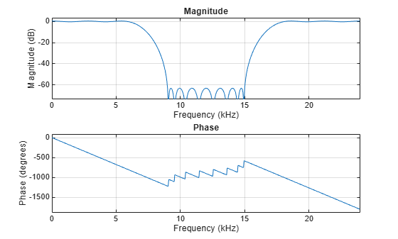
Create Sinusoidal Signal
Create a signal that is a sum of three sinusoids with frequencies at 1 kHz, 12 kHz, and 16 kHz. Initialize Spectrum Analyzer to view the original signal and the filtered signal.
Sine1 = dsp.SineWave(Frequency=1e3,SampleRate=44.1e3,SamplesPerFrame=4000);
Sine2 = dsp.SineWave(Frequency=12e3,SampleRate=44.1e3,SamplesPerFrame=4000);
Sine3 = dsp.SineWave(Frequency=16e3,SampleRate=44.1e3,SamplesPerFrame=4000);

SpecAna = spectrumAnalyzer(PlotAsTwoSidedSpectrum=false, ...
    SampleRate=Sine1.SampleRate, ...
    ShowLegend=true, ...
    YLimits=[-240,45]);

SpecAna.ChannelNames = {'Original noisy signal','Filtered signal'};
Filter Sinusoidal Signal
Filter the sinusoidal signal using the bandstop filter that has been designed. View the original signal and the filtered signal in the Spectrum Analyzer. The tone at 1 kHz is unaffected. The tone at 12 kHz is filtered out and attenuated, and the tone at 16 kHz is mildly attenuated because it appears in the transition band of the filter.
for i = 1 : 10000
    x = Sine1()+Sine2()+Sine3();
    y = bsFilter(x);
    SpecAna(x,y);
end
release(SpecAna)

Input Arguments
Specification expression, specified as one of these character vectors:
'Fp1,Fst1,Fst2,Fp2,Ap1,Ast,Ap2'(default)'N,F3dB1,F3dB2''N,F3dB1,F3dB2,Ap'*'N,F3dB1,F3dB2,Ap,Ast'*'N,F3dB1,F3dB2,Ast'*'N,F3dB1,F3dB2,BWp'*'N,F3dB1,F3dB2,BWst'*'N,Fc1,Fc2''N,Fc1,Fc2,Ap1,Ast,Ap2''N,Fp1,Fp2,Ap''N,Fp1,Fp2,Ap,Ast''N,Fp1,Fst1,Fst2,Fp2''N,Fp1,Fst1,Fst2,Fp2,C'*'N,Fp1,Fst1,Fst2,Fp2,Ap'*'N,Fst1,Fst2,Ast''Nb,Na,Fp1,Fst1,Fst2,Fp2'*
This table describes each option that can appear in the expression.
| Specification option | Description |
|---|---|
Ap | Amount of ripple allowed in passband, specified as
Apass in dB. |
Ap1 | Amount of ripple allowed in the first passband, specified
as Apass1 in dB. |
Ap2 | Amount of ripple allowed in the second passband,
specified as Apass2 in dB. |
Ast | Stopband attenuation (dB), specified using
Astop. |
BWp | Bandwidth of the filter passband, specified as
BWpass in normalized frequency
units. |
BWst | Bandwidth of the filter stopband, specified as
BWstop in normalized frequency
units. |
F3dB1 | Frequency of the 3 dB point below the passband value for the first cutoff, specified in normalized frequency units. Applies to IIR filters. |
F3dB2 | Frequency of the 3 dB point below the passband value for the second cutoff, specified in normalized frequency units. Applies to IIR filters. |
Fc1 | First cutoff frequency (normalized frequency units),
specified using Fcutoff1. Applies to
FIR filters. |
Fc2 | Second cutoff frequency (normalized frequency units),
specified using Fcutoff1. Applies to
FIR filters. |
Fp1 | Frequency at the start of the pass band, specified as
Fpass1 in normalized frequency
units. |
Fp2 | Frequency at the end of the pass band, specified as
Fpass2 in normalized frequency
units. |
Fst1 | Frequency at the end of the first stop band, specified as
Fstop1 in normalized frequency
units. |
Fst2 | Frequency at the start of the second stop band, specified
as Fstop2 in normalized frequency
units. |
N | Filter order for FIR filters. Or both the numerator and
denominator orders for IIR filters when
Na and Nb are not
provided. Specified using
FilterOrder. |
Nb | Numerator order for IIR filters, specified using the
DenOrder property. |
Na | Denominator order for IIR filters, specified using the
NumOrder property. |
C | Constrained band flag. This enables you to specify passband ripple or stopband attenuation for fixed-order designs in one or two of the three bands. In
the specification
|
Graphically, the filter specifications look similar to those shown in the following figure.

Regions between specification values like Fp1 and
Fst1 are transition regions where the filter response
is not explicitly defined.
The design methods available for designing the filter depend on the
specification expression. You can obtain these methods using the designmethods function. The
table lists each specification expression supported by
fdesign.bandstop and the corresponding design
methods available.
| Specification expression | Supported design methods |
|---|---|
'Fp1,Fst1,Fst2,Fp2,Ap1,Ast,Ap2' | butter, cheby1,
cheby2, ellip,
equiripple,
kaiserwin |
'N,F3dB1,F3dB2' | butter |
'N,F3dB1,F3dB2,Ap' | cheby1 |
'N,F3dB1,F3dB2,Ap,Ast' | ellip |
'N,F3dB1,F3dB2,Ast' | cheby2,
ellip |
'N,F3dB1,F3dB2,BWp' | cheby1 |
'N,F3dB1,F3dB2,BWst' | cheby2 |
'N,Fc1,Fc2' | window |
'N,Fc1,Fc2,Ap1,Ast,Ap2' | fircls |
'N,Fp1,Fp2,Ap' | cheby1 |
'N,Fp1,Fp2,Ap,Ast' | ellip |
'N,Fp1,Fst1,Fst2,Fp2' | iirlpnorm,
equiripple,
firls |
'N,Fp1,Fst1,Fst2,Fp2,C' | equiripple |
'N,Fp1,Fst1,Fst2,Fp2,Ap' | ellip |
'N,Fst1,Fst2,Ast' | cheby2 |
'Nb,Na,Fp1,Fst1,Fst2,Fp2' | iirlpnorm |
To design the filter, call the design function with one of
these design methods as an input. You can choose the type of filter response
by passing 'FIR' or 'IIR' to the
design function. For more details, see design. Enter
help(bandstopSpecs,'method') at the MATLAB® command line to obtain detailed help on the design options for
a given design method, 'method'.
For more details on the procedure, see Filter Design Procedure. For an example, see Design Notch Filter.
Specification values, specified as a comma-separated list of values.
Specify a value for each option in spec in the same
order that the options appear in the expression.
Example: bandstopSpecs =
fdesign.bandstop('N,Fp1,Fst1,Fst2,Fp2,C',n,fp1,fst1,fst2,fp2,c)
The arguments below describe more details for each option in the expression.
Filter order for FIR filters, specified as a positive integer.
In the case of IIR filter design, if nb and
na are not provided, this value is
interpreted as both the numerator order and the denominator
order.
Data Types: single | double | int8 | int16 | int32 | int64 | uint8 | uint16 | uint32 | uint64
Numerator order for IIR filters, specified as a nonnegative integer.
Data Types: single | double | int8 | int16 | int32 | int64 | uint8 | uint16 | uint32 | uint64
Denominator order for IIR filters, specified as a positive integer.
Data Types: single | double | int8 | int16 | int32 | int64 | uint8 | uint16 | uint32 | uint64
This enables you to specify passband ripple or stopband attenuation for fixed-order designs in one or two of the three bands.
In the specification
'N,Fp1,Fst1,Fst2,Fp2,C', you cannot
specify constraints for all three bands (two passbands and one
stopband) simultaneously. You can specify constraints in any one
or two bands.
Consider the following bandstop design specification where both the passbands are constrained to the default value, 1 dB.
Example: spec =
fdesign.bandstop('N,Fp1,Fst1,Fst2,Fp2,C',10,0.35,0.45,0.55,0.65);
spec.Passband1Constrained=true;
spec.Passband2Constrained=true;
Passband ripple, specified as a positive scalar in dB. If
magunits is 'linear'
or 'squared', the passband ripple is
converted and stored in dB by the function regardless of how it
has been specified.
The specified ap value applies to both
the first passband and the second passband.

Data Types: single | double | int8 | int16 | int32 | int64 | uint8 | uint16 | uint32 | uint64
Amount of ripple allowed in the first passband, specified as a
positive scalar in dB. If magunits is
'linear' or 'squared',
the first passband ripple is converted and stored in dB by the
function regardless of how it has been specified.
Data Types: single | double | int8 | int16 | int32 | int64 | uint8 | uint16 | uint32 | uint64
Amount of ripple allowed in the second passband, specified as
a positive scalar in dB. If magunits is
'linear' or 'squared',
the second passband ripple is converted and stored in dB by the
function regardless of how it has been specified.
Data Types: single | double | int8 | int16 | int32 | int64 | uint8 | uint16 | uint32 | uint64
Stopband attenuation, specified as a positive scalar in dB. If
magunits is 'linear'
or 'squared', the stopband attenuation is
converted and stored in dB by the function regardless of how it
has been specified.

Data Types: single | double | int8 | int16 | int32 | int64 | uint8 | uint16 | uint32 | uint64
Bandwidth of the filter passband in normalized frequency units, specified as a positive scalar.
Data Types: single | double | int8 | int16 | int32 | int64 | uint8 | uint16 | uint32 | uint64
First 3 dB frequency, specified as positive scalar in normalized frequency units.
This is the frequency of the 3 dB point below the passband value for the first cutoff. Applies to IIR filters only.

Data Types: single | double | int8 | int16 | int32 | int64 | uint8 | uint16 | uint32 | uint64
Second 3 dB frequency, specified as positive scalar in normalized frequency units.
This is the frequency of the 3 dB point below the passband value for the second cutoff. Applies to IIR filters only.
Data Types: single | double | int8 | int16 | int32 | int64 | uint8 | uint16 | uint32 | uint64
First cutoff frequency, specified as positive scalar in normalized frequency units.
Applies to FIR filters only.

Data Types: single | double | int8 | int16 | int32 | int64 | uint8 | uint16 | uint32 | uint64
Second cutoff frequency, specified as positive scalar in normalized frequency units.
Applies to FIR filters only.
Data Types: single | double | int8 | int16 | int32 | int64 | uint8 | uint16 | uint32 | uint64
First stopband frequency, specified as positive scalar in normalized frequency units.
This is the frequency at the start of the stopband.
Data Types: single | double | int8 | int16 | int32 | int64 | uint8 | uint16 | uint32 | uint64
Second stopband frequency, specified as positive scalar in normalized frequency units.
This is the frequency at the end of the stopband.
Data Types: single | double | int8 | int16 | int32 | int64 | uint8 | uint16 | uint32 | uint64
First passband frequency, specified as positive scalar in normalized frequency units.
This is the frequency at the end of the first passband.
Data Types: single | double | int8 | int16 | int32 | int64 | uint8 | uint16 | uint32 | uint64
Second passband frequency, specified as positive scalar in normalized frequency units.
This is the frequency at the start of the second passband.
Data Types: single | double | int8 | int16 | int32 | int64 | uint8 | uint16 | uint32 | uint64
Sample rate of the signal to be filtered, specified as a scalar in Hz.
Specify the sample rate as a scalar trailing the other numerical values
provided. When Fs is provided, Fs
is assumed to be in Hz, as are all other frequency values provided. Note
that you do not have to change the specification string.
The following design has the specification string set to
'Fp1,Fst1,Fst2,Fp2,Ap1,Ast,Ap2', and sample rate set
to 8000 Hz.
bandstopSpecs =
                            fdesign.bandstop('Fp1,Fst1,Fst2,Fp2,Ap1,Ast,Ap2',1600,2000,2400,2800,1,80,.5,8000);
                            filt = design(bandstopSpecs,'Systemobject',true);
Data Types: single | double | int8 | int16 | int32 | int64 | uint8 | uint16 | uint32 | uint64
Magnitude specification units, specified as 'dB',
'linear', or 'squared'. If this
argument is omitted, 'dB' is assumed. Note that the
magnitude specifications are always converted and stored in dB regardless of
how they were specified. If Fs is one of the input
arguments, magunits must be specified after
Fs in the input argument list.
Output Arguments
Bandstop filter design specification object, returned as a
bandstop object. The fields of the object depend on the
spec input character vector.
Consider an example where the spec argument is set to
'N,Fc1,Fc2', and the corresponding values are set to
10, 0.6, and
0.8, respectively. The bandstop
filter design specification object is populated with the following fields:

Version History
Introduced in R2009a