Differentiator Filter
Direct form FIR fullband differentiator filter
Libraries:
DSP System Toolbox /
Filtering /
Filter Designs
Description
The Differentiator Filter block applies a fullband differentiator filter on the input signal to differentiate all its frequency components. The block uses an FIR equiripple filter design to design the differentiator filter. The ideal frequency response of the differentiator is for .
You can design the filter with a minimum order or with a specific order.
This block also supports SIMD code generation. For details, see Code Generation.
Examples
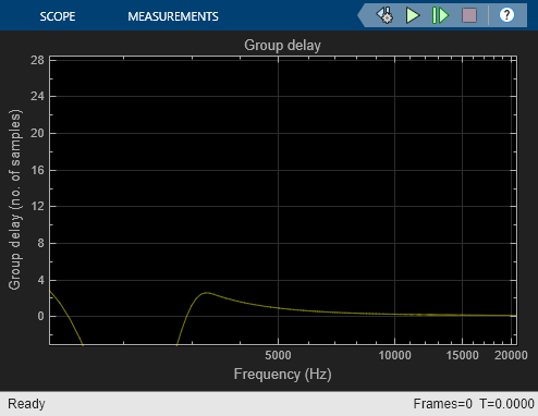
Group Delay Estimation in Simulink
Estimate the group delay of a filter in Simulink®.
Ports
Input
Output
Parameters
Main Tab
When you select this check box, the block designs a filter with the minimum order and with the passband ripple that you specify in Maximum passband ripple (dB). When you clear this check box, specify the order of the filter in Filter order.
Specify the order of the differentiator filter as an odd positive integer.
Dependencies
To enable this parameter, clear the Design minimum order filter parameter.
Specify the maximum ripple of the filter response in the passband as a real positive scalar in dB.
When you select this check box, the blocks scales the filter coefficients to preserve the input dynamic range. By default, this check box is not selected.
Click this button to open the Filter Visualization Tool
(fvtool) and display the magnitude and phase
response of the Differentiator Filter block. The response
is based on the block dialog box parameters. Changes made to these
parameters update FVTool.
To update the magnitude response while FVTool is running, modify the dialog box parameters and click Apply.
Specify the type of simulation to run. You can set this parameter to:
Interpreted execution(default)Simulate model using the MATLAB® interpreter. This option shortens startup time and has faster simulation speed than
Code generation.Code generationSimulate model using generated C code. The first time you run a simulation, Simulink® generates C code for the block. The C code is reused for subsequent simulations, as long as the model does not change. This option requires additional startup time but provides faster subsequent simulations.
Data Types Tab
Specify the rounding method for the output fixed-point operations. The rounding methods
are Ceiling,
Convergent,
Floor,
Nearest, Round,
Simplest, and
Zero. The default is
Floor.
Specify the fixed-point data type of the coefficients as one of the following:
fixdt(1,16)— Signed fixed-point data type of word length16with binary point scaling. The block determines the fraction length automatically from the coefficient values such that the coefficients occupy the maximum representable range without overflowing.fixdt(1,16,0)— Signed fixed-point data type of word length16and fraction length0. You can change the fraction length to any other integer value.<data type expression>— Specify the data type using an expression that evaluates to a data type object, for example, numeric type (fixdt([ ],16,15)). Specify the sign mode of this data type as[ ]ortrue.Refresh Data Type— Refresh to the default data type.
Click the Show data type assistant
button ![]() to display the data type assistant,
which helps you set the stage input parameter.
to display the data type assistant,
which helps you set the stage input parameter.
See Specify Data Types Using Data Type Assistant (Simulink) for more information.
The word length of the output is same as the word length of the input. The fraction length of the output is computed such that the entire dynamic range of the output can be represented without overflow. For details on how the block computes the fraction length, see Fixed-Point Precision Rules for Avoiding Overflow in FIR Filters.
Block Characteristics
Data Types |
|
Direct Feedthrough |
|
Multidimensional Signals |
|
Variable-Size Signals |
|
Zero-Crossing Detection |
|
Algorithms
Differentiator computes the derivative of a signal. The frequency response of an ideal differentiator filter is given by , defined over the Nyquist interval .

The frequency response is antisymmetric and is linearly proportional to the frequency.
dsp.Differentiator object acts as a differentiator
filter. This object condenses the two-step process into one. For the
minimum order design, the object uses generalized Remez FIR filter
design algorithm. For the specified order design, the object uses
the Parks-McClellan optimal equiripple FIR filter design algorithm.
The filter is designed as a linear phase Type-IV FIR filter with a
Direct form structure.
The ideal differentiator has an antisymmetric impulse response given by . Hence . The differentiator must have zero response at zero frequency.
Linear-Phase FIR Differentiator Filter
The impulse response of an antisymmetric linear-phase FIR filter is given by , where M is the length of the filter. Because the filter is antisymmetric, you can use this type of FIR filter to design the linear-phase FIR differentiators.
Consider the design of linear-phase FIR differentiators based on the Chebyshev approximation criterion.
If M is odd, the real-valued frequency response of the FIR filter, Hr(ω), has the characteristics that Hr(0) = 0 and Hr(π) = 0. This filter satisfies the condition of zero response at zero frequency. However, it is not fullband because Hr(π) = 0. This differentiator has a linear response over the limited frequency range [0 2πfp], where fp is the bandwidth of the differentiator. The absolute error between the desired response and the Chebyshev approximation increases as ω increases from 0 to 2πfp.
If M is even, the real-valued frequency response of the FIR filter, Hr(ω), has the characteristics that Hr(0) = 0 and Hr(π) ≠ 0. This filter satisfies the condition of zero response at zero frequency. It is fullband and this design results in a significantly smaller approximation error than comparable odd-length differentiators. Hence, even-length (odd order) differentiators are preferred in practical systems.
Extended Capabilities
Version History
Introduced in R2015b