Fixed-Point Precision Rules for Avoiding Overflow in FIR Filters
Fixed-point FIR filters are commonly implemented on digital signal processors, FPGAs, and ASICs. A fixed-point filter uses fixed-point arithmetic and is represented by an equation with fixed-point coefficients. If the accumulator and output of the FIR filter do not have sufficient bits to represent their data, overflow occurs and distorts the signal. Use these two rules to determine FIR filter precision settings automatically. The aim is to minimize resource utilization (memory/storage and processing elements) while avoiding overflow. Because the rules are optimized based on the input precision, coefficient precision, and the coefficient values, the FIR filter must have nontunable coefficients.
The precision rules define the minimum and the maximum values of the FIR filter output. To determine these values, perform min/max analysis on the FIR filter coefficients.
Output Limits for FIR Filters
FIR filter is defined by:
x[n] is the input signal.
y[n] is the output signal.
hk is the kth filter coefficient.
N is the length of the filter.
Output Limits for FIR Filters with Real Input and Real Coefficients
Let the minimum value of the input signal be Xmin, where Xmin ≤ 0, and the maximum value be Xmax, where Xmax ≥ 0. The minimum output occurs when you multiply the positive coefficients by Xmin and the negative coefficients by Xmax. Similarly, the maximum output occurs when you multiply the positive coefficients by Xmax and the negative coefficients by Xmin.
If the sum of all the positive coefficients is
and the sum of all the negative coefficients is denoted as
then you can express the minimum output of the filter as
and the maximum output of the filter as
Therefore, the output of the filter lies in the interval [Ymin, Ymax].
Complex Filter Convolution Equations
You can define a complex filter (complex inputs and complex coefficients) in terms of the real and imaginary parts of its signals and coefficients:
The complex filter is decomposed into four real filters as depicted in the signal flow diagram. Each signal is annotated with an interval denoting its range.
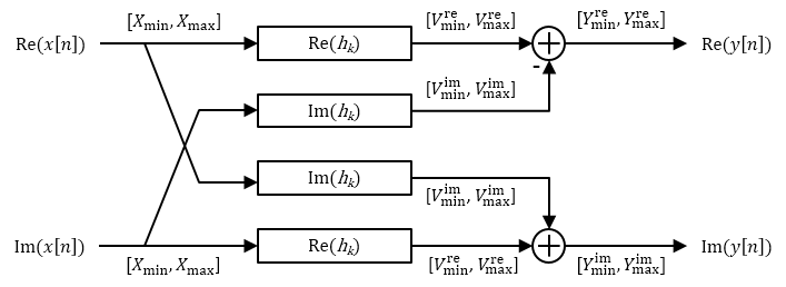
Output Limits for FIR Filters with Complex Input and Complex Coefficients
You can extend the real filter min/max analysis to complex filters. Assume that both the real and imaginary parts of the input signal lie in the interval [Xmin, Xmax].
The complex filter contains two instances of the filter Re(hk). Both filters have the same input range and therefore the same output range in the interval [Vremin, Vremax]. Similarly, the complex filter contains two instances of the filter Im(hk). Both filters have the same output range in the interval [Vimmin, Vimmax].
Based on the min/max analysis of real filters, you can express Vremin, Vremax, Vimmin, and Vimmax as:
G+re is the sum of the positive real parts of hk, given by
G-re is the sum of the negative real parts of hk, given by
G+im is the sum of the positive imaginary parts of hk, given by
G-im is the sum of the negative imaginary parts of hk, given by
The minimum and maximum values of the real and imaginary parts of the output are:
The worst-case minimum and maximum on either the real or imaginary part of the output is given by
Fixed-Point Precision Rules
The fixed-point precision rules define the output word length and fraction length of the filter in terms of the accumulator word length and fraction length.
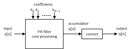
Full-Precision Accumulator Rule
Assume that the input is a signed or unsigned fixed-point signal with word length Wx and fraction length Fx. Also assume that the coefficients are signed or unsigned fixed-point values with fraction length Fh. You can now define full precision as the fixed-point settings that minimize the word length of the accumulator while avoiding overflow or any loss of precision.
The accumulator fraction length is equal to the product fraction length, which is the sum of the input and coefficient fraction lengths.
If Ymin = 0, then the accumulator is unsigned with word length
If Ymin < 0, then the accumulator is signed with word length
The ceil operator rounds to the nearest integer towards +∞.
Output Same Word Length as Input Rule
This rule sets the output word length to be the same as the input word length. Then, it adjusts the fraction length to avoid overflow. Wq is the output word length and Fq is the output fraction length.
Truncate the accumulator to make the output word length same as the input word length.
.
Set the output fraction length Fq to
.
Polyphase Interpolators and Decimators
You can extend these rules to polyphase FIR interpolators and decimators.
FIR Interpolators
Treat each polyphase branch of the FIR interpolator as a separate FIR filter. The output data type of the FIR interpolator is the worst-case data type of all the polyphase branches.
FIR Decimators
For decimators, the polyphase branches add up at the output. Hence, the output data type is computed as if it were a single FIR filter with all the coefficients of all the polyphase branches.