Control System Designer
Entwurf von Reglern mit einem Eingang und einem Ausgang (SISO)
Beschreibung
Mit der App Control System Designer können Sie Reglern mit einem Eingang und einem Ausgang (SISO) für Feedback-Systeme entwerfen, die in MATLAB® oder Simulink® (erfordert die Software Simulink Control Design™) modelliert wurden.
Mithilfe dieser App können Sie:
Regler entwerfen mit:
Interaktive grafische Bode-, Wurzelort- und Nichols-Editoren zum Hinzufügen, Ändern und Entfernen von Reglerpolen, Nullstellen und Verstärkungen
Automatisierte PID-, LQG- oder IMC-Abstimmung
Optimierungsbasierte Abstimmung (erfordert Simulink Design Optimization™ Software)
Automatisierte Schleifenformung
Kompensatoren für Regelungsarchitekturen mit einer oder mehreren Schleifen optimieren
Regelungssysteme anhand von Zeit- und Frequenzbereichsantworten, wie z. B. Sprungantworten und Pol-Nullstellen-Zuordnungen analysieren
Antwortdiagramme für mehrere Regelsystementwürfe vergleichen
Regler für Regelungsanwendungen mit mehreren Modellen entwickeln

Öffnen Sie die Control System Designer-App
MATLAB Toolstrip: Klicken Sie auf der Registerkarte Apps unter Control System Design and Analysis auf das App-Symbol.
MATLAB-Eingabeaufforderung: Geben Sie
controlSystemDesignerein.Simulink Toolstrip: Klicken Sie auf der Registerkarte Apps unter Control Systems auf das App-Symbol.
Beispiele
Nachdem Sie Ihren Regler in Control System Designer entworfen haben, können Sie Ihren Entwurf in den MATLAB-Workspace für weitere Analysen oder Entwürfe exportieren.
Klicken Sie in Control System Designer auf der Registerkarte Control System unter Export auf Export tuned blocks.
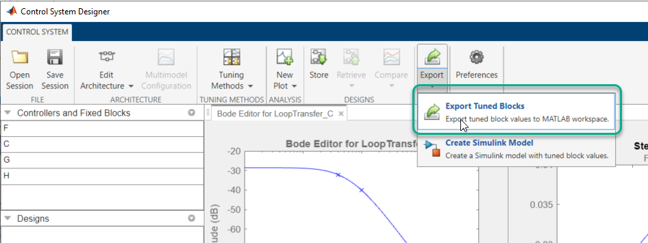
Wählen Sie im Dialogfeld „Export Model“ (Modell exportieren) in der Auswahlliste Select Design den Entwurf aus, den Sie exportieren möchten. Sie können entweder den aktuellen Entwurf, Current Design, oder einen der gespeicherten Entwürfe aus dem Data Browser auswählen.
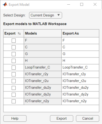
Wählen Sie in der Tabelle Export models to MATLAB Workspace in der Spalte Export die Modelle aus, die Sie exportieren möchten.
Für alle Entwürfe können Sie den Regler exportieren und die Modelle vorfiltern. Zudem können Sie für Current Design die festen Blockmodelle und alle Antworten aus dem Data Browser exportieren.
Weitere Informationen zu den Vorfiltern, Reglern und festen Blöcken in jeder der Regelungsarchitekturen finden Sie unter Feedback Control Architectures in Control System Designer.
In der Spalte Export as können Sie einen alternativen Namen für das exportierte Modell angeben. Der Export eines Modells mit demselben Namen wie eine bestehende Variable im MATLAB-Workspace überschreibt die Variable.
Um die ausgewählten Modelle im MATLAB-Workspace zu speichern, klicken Sie auf Export.
Nach dem Entwurf Ihrer Regler in Control System Designer können Sie automatisch ein Simulink-Modell für Ihre Regelungsarchitektur erstellen, um Ihr System zu simulieren.
Klicken Sie auf der Registerkarte Control System unter Export auf Create Simulink Model.
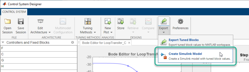
Die App exportiert die Regler und festen Blöcke für den aktuellen Entwurf in den MATLAB-Workspace und erzeugt ein Simulink-Modell, das der aktuellen Regelungsarchitektur entspricht. Weitere Informationen zu den Reglern und festen Blöcken in jeder der Regelungsarchitekturen finden Sie unter Feedback Control Architectures in Control System Designer.
Wenn Sie zum Beispiel ein Regelungssystem entsprechend Konfiguration 1 entwerfen, exportiert Control System Designer C, F, G und H in den MATLAB-Workspace und erzeugt das folgende Simulink-Modell.
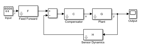
In dem erstellten Modell ist der Input-Block ein Signalgeneratorblock, Signal Generator (Simulink). Mit diesem Block simulieren Sie Ihr Modell mit verschiedenen Eingangswellenformen, wie z. B. Sinuswellen oder Zufallssignalen. Um eine Sprungantwort zu erzeugen, ersetzen Sie den Input-Block durch einen Step (Simulink)-Block.
Um ein Simulink-Modell für einen gespeicherten Entwurf zu erstellen, machen Sie diesen Entwurf zunächst aktuell. Wählen Sie auf der Registerkarte Control System unter Retrieve den Entwurf aus, für den Sie ein Modell erstellen möchten.
Verwandte Beispiele
Programmatische Nutzung
controlSystemDesigner öffnet die App Control System Designer mithilfe der folgenden Standard-Regelungsarchitektur:

Die Architektur besteht aus den LTI-Objekten:
G – Regelstreckenmodell
C – Kompensator
H – Sensormodell
F – Vorfilter
Standardmäßig konfiguriert die App jedes dieser Modelle als Verstärkungsfaktor Eins.
controlSystemDesigner( initialisiert den Kompensator C auf das SISO-LTI-Modell plant,comp)comp.
controlSystemDesigner( initialisiert das Sensormodell H auf plant,comp,sensor)sensor. sensor kann ein beliebiges SISO-LTI-Modell sein oder ein Array solcher Modelle. Wenn Sie sowohl plant als auch sensor als LTI-Modell-Arrays angeben, müssen die Längen der Arrays übereinstimmen.
controlSystemDesigner( initialisiert das Vorfiltermodell F auf das SISO-LTI-Modell plant,comp,sensor,prefilt)prefilt.
controlSystemDesigner( öffnet die App und legt die Ausgangskonfiguration des grafischen Editors fest. views)views kann einer der folgenden Zeichenvektoren oder ein Zellenarray mit mehreren Zeichenvektoren sein.
"rlocus"– Wurzelort-Editor"bode"– Bode-Editor des offenen Regelkreises"nichols"– Nichols-Editor des offenen Regelkreises"filter"– Bode-Editor für die Antwort des geschlossenen Regelkreises vom Vorfiltereingang zum Regelstreckenausgang
Die App öffnet nicht nur die angegebenen grafischen Editoren, sondern stellt auch die Eingangs-/Ausgangs-Sprungantwort des geschlossenen Regelkreises dar.
controlSystemDesigner( legt die Ausgangskonfiguration des Diagramms fest und initialisiert die Regelstrecke, den Kompensator, den Sensor und den Vorfilter unter Verwendung der angegebenen Modelle. Wenn ein Modell nicht angegeben wird, verwendet die App den Standardwert.views,plant,comp,sensor,prefilt)
controlSystemDesigner( öffnet die App und initialisiert die Systemkonfiguration mithilfe der Datenstruktur für die Initialisierung initData)initdata. Zum Erstellen von initdata verwenden Sie sisoinit.
controlSystemDesigner( öffnet die App und lädt eine zuvor gespeicherte Sitzung. sessionFile)sessionFile ist der Name einer Sitzungsdatendatei auf dem MATLAB-Pfad. Diese Daten umfassen die aktuelle Systemarchitektur und Diagrammkonfiguration sowie alle im Data Browser gespeicherten Entwürfe und Antworten.
Klicken Sie zum Speichern einer Sitzung in der App Control System Designer auf der Registerkarte Control System auf  Save Session.