Mapped CI Engine
Compression-ignition engine model using lookup tables

Libraries:
Powertrain Blockset /
Propulsion /
Combustion Engines
Vehicle Dynamics Blockset /
Powertrain /
Propulsion
Description
The Mapped CI Engine block implements a mapped compression-ignition (CI) engine model using power, air mass flow, fuel flow, exhaust temperature, efficiency, and emission performance lookup tables. You can use the block for:
Hardware-in-the-loop (HIL) engine control design
Vehicle-level fuel economy and performance simulations
The lookup tables, developed with the Model-Based Calibration Toolbox™, are functions of injected fuel mass, F, engine torque, T, engine speed, N, and engine temperature, TempEng.
Input Command Setting | Input Engine Temperature Parameter Setting | Lookup Tables |
|---|---|---|
Fuel mass | off | ƒ(F,N) |
on | ƒ(F,N,TempEng) | |
Torque | off | ƒ(T,N) |
on | ƒ(T,N,TempEng) |
The block enables you to specify lookup tables for these engine characteristics:
Power
Air
Fuel
Temperature
Efficiency
Hydrocarbon (HC) emissions
Carbon monoxide (CO) emissions
Nitric oxide and nitrogen dioxide (NOx) emissions
Carbon dioxide (CO2) emissions
Particulate matter (PM) emissions
To bound the Mapped CI Engine block output, the block does not extrapolate the lookup table data.
Virtual Calibration
If you have Model-Based Calibration Toolbox, click Calibrate Maps to virtually calibrate the 2D lookup tables using measured data. The dialog box steps through these tasks.
Task | Description | ||||||||
|---|---|---|---|---|---|---|---|---|---|
Import firing data | Import this loss data from a file. For example, open
For more information, see Using Data (Model-Based Calibration Toolbox).
Collect firing data at steady-state operating conditions when injectors deliver the fuel. Data should cover the engine speed and torque operating range. Model-Based Calibration Toolbox uses the firing data boundary as the maximum torque. To filter or edit the data, select Edit in Application. The Model-Based Calibration Toolbox Data Editor opens. | ||||||||
Import non-firing data | Import this non-firing data from a file. For example, open
Collect non-firing (motoring) data at steady-state operating conditions when fuel is cut off. All non-firing torque points must be less than zero. Non-firing data is a function of engine speed only. | ||||||||
Generate response models | For both firing and non-firing data, the Model-Based Calibration Toolbox uses test plans to fit data to Gaussian process models (GPMs). To assess or adjust the response model fit, select Edit in Application. The Model-Based Calibration Toolbox Model Browser opens. For more information, see Model Assessment (Model-Based Calibration Toolbox). | ||||||||
Generate calibration | Model-Based Calibration Toolbox calibrates the firing and non-firing response models and generates calibrated tables. To assess or adjust the calibration, select Edit in Application. The Model-Based Calibration Toolbox CAGE Browser opens. For more information, see Calibration Lookup Tables (Model-Based Calibration Toolbox). | ||||||||
Update block parameters | Update the block lookup table and breakpoint parameters with the calibration. |
Cylinder Air Mass
The block calculates the normalized cylinder air mass using these equations.
The equations use these variables.
| L | Normalized cylinder air mass |
Nominal engine cylinder air mass at standard temperature and pressure, piston at bottom dead center (BDC) maximum volume, in kg | |
Crankshaft revolutions per power stroke, rev/stroke | |
| Standard pressure | |
| Standard temperature | |
Ideal gas constant for air and burned gas mixture | |
Displaced volume | |
Number of engine cylinders | |
| N | Engine speed |
Engine air mass flow, in g/s |
Turbocharger Lag
To model turbocharger lag, select Include turbocharger lag effect. Turbocharger lag limits the maximum fuel mass per injection. To model the maximum fuel mass per injection, the block uses a first-order system with a time constant. At low torque, the engine does not require boost to provide sufficient air flow. When the requested fuel mass requires boost, the block uses a time constant to determine the maximum fuel mass per injection. The block uses these equations for the specified Input command setting.
| Calculation | Input command Parameter Setting | |
|---|---|---|
Fuel mass | Torque | |
Dynamic torque |
|
|
Fuel mass per injection or torque - with turbocharger lag |
|
|
Fuel mass per injection or torque- without turbocharger lag |
|
|
Boost time constant |
|
|
Final time constant |
| |
The equations use these variables.
| Tbrake |
Brake torque |
| F |
Fuel mass per injection |
| Fcmd, Fmax |
Commanded and maximum fuel mass per injection, respectively |
| Ttarget, Tcmd, Tmax |
Target, commanded, and maximum torque, respectively |
| τbst |
Boost time constant |
| τbst,rising, τbst,falling |
Boost rising and falling time constant, respectively |
| τeng |
Final time constant |
| τnat | Time constant below the boost torque speed line |
| ƒbst(N) | Boost torque/speed line |
| N | Engine speed |
Fuel Flow
To calculate the fuel economy for high-fidelity models, the block uses the volumetric fuel flow.
The equation uses these variables.
| Fuel mass flow | |
| Sgfuel | Specific gravity of fuel |
| Qfuel | Volumetric fuel flow |
Power Accounting
For the power accounting, the block implements these equations.
| Bus Signal | Description | Equations | ||
|---|---|---|---|---|
|
|
| Crankshaft power | |
|
|
| Fuel input power | ||
| Power loss | |||
|
| Not used | |||
The equations use these variables.
LHV | Fuel lower heating value |
ω | Engine speed, rad/s |
| Fuel mass flow | |
τeng | Fuel mass per injection time constant |
Examples
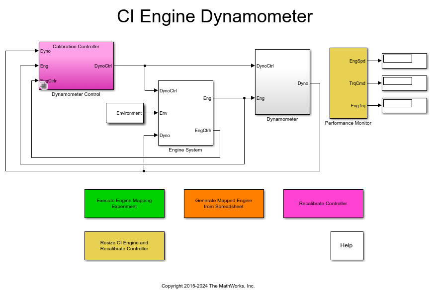
CI Engine Dynamometer Reference Application
Simulate a compression-ignition (CI) engine and controller under a dynamometer test harness using the CI engine dynamometer reference application.
Ports
Input
Injected fuel mass command, F, in mg/inj.
Dependencies
To enable this port, for Input command,
select Fuel mass.
Torque command, T, in N·m.
Dependencies
To enable this port, for Input command,
select Torque.
Engine speed, N, in rpm.
Engine temperature, TempEng, in K.
Dependencies
To enable this port, select Input engine temperature.
Output
Bus signal containing these block calculations.
| Signal | Description | Units | ||
|---|---|---|---|---|
| Engine air mass flow output | kg/s | ||
| Normalized engine cylinder air mass | N/A | ||
| Air-fuel ratio (AFR) | N/A | ||
| Engine fuel flow output | kg/s | ||
| Volumetric fuel flow | m3/s | ||
| Engine exhaust gas temperature | K | ||
| Engine torque output | N·m | ||
| Engine speed | rpm | ||
| Engine crankshaft absolute angle where is crankshaft revolutions per power stroke. | degrees crank angle | ||
| Engine brake-specific fuel consumption (BSFC) | g/kWh | ||
| Engine out hydrocarbon emission mass flow | kg/s | ||
| Engine out carbon monoxide emission mass flow rate | kg/s | ||
| Engine out nitric oxide and nitrogen dioxide emissions mass flow | kg/s | ||
| Engine out carbon dioxide emission mass flow | kg/s | ||
| Engine out particulate matter emission mass flow | kg/s | ||
PwrInfo | PwrTrnsfrd | PwrCrkshft | Crankshaft power | W |
PwrNotTrnsfrd | PwrFuel | Fuel input power | W | |
PwrLoss | Power loss | W | ||
PwrStored | Not used | |||
Engine power, , in N·m.
Parameters
Block Options
The lookup tables, developed with the Model-Based Calibration Toolbox, are functions of injected fuel mass, F, engine torque, T, engine speed, N, and engine temperature, TempEng.
Input Command Setting | Input Engine Temperature Parameter Setting | Lookup Tables |
|---|---|---|
Fuel mass | off | ƒ(F,N) |
on | ƒ(F,N,TempEng) | |
Torque | off | ƒ(T,N) |
on | ƒ(T,N,TempEng) |
Programmatic Use
To set the block parameter value programmatically, use
the set_param function.
To get the block parameter value
programmatically, use the get_param function.
| Parameter: | InputCmdPopup |
| Values: | Fuel mass (default) | Torque |
| Data Types: | character vector |
Dependencies
Selecting
Fuel massenables Breakpoints for commanded fuel mass input, f_tbrake_f_bpt.Selecting
Torqueenables Breakpoints for commanded torque input, f_tbrake_t_bpt.Selecting Input engine temperature enables Breakpoints for temperature input, f_tbrake_engtmp_bpt.
To model turbocharger lag, select Include turbocharger lag effect. Turbocharger lag limits the maximum fuel mass per injection. To model the maximum fuel mass per injection, the block uses a first-order system with a time constant. At low torque, the engine does not require boost to provide sufficient air flow. When the requested fuel mass requires boost, the block uses a time constant to determine the maximum fuel mass per injection. The block uses these equations for the specified Input command setting.
| Calculation | Input command Parameter Setting | |
|---|---|---|
Fuel mass | Torque | |
Dynamic torque |
|
|
Fuel mass per injection or torque - with turbocharger lag |
|
|
Fuel mass per injection or torque- without turbocharger lag |
|
|
Boost time constant |
|
|
Final time constant |
| |
The equations use these variables.
| Tbrake |
Brake torque |
| F |
Fuel mass per injection |
| Fcmd, Fmax |
Commanded and maximum fuel mass per injection, respectively |
| Ttarget, Tcmd, Tmax |
Target, commanded, and maximum torque, respectively |
| τbst |
Boost time constant |
| τbst,rising, τbst,falling |
Boost rising and falling time constant, respectively |
| τeng |
Final time constant |
| τnat | Time constant below the boost torque speed line |
| ƒbst(N) | Boost torque/speed line |
| N | Engine speed |
Programmatic Use
To set the block parameter value programmatically, use
the set_param function.
To get the block parameter value
programmatically, use the get_param function.
| Parameter: | TurboLagCheckbox |
| Values: | off (default) | on |
| Data Types: | character vector |
Dependencies
Selecting Include turbocharger lag effect enables these parameters:
Boost torque line, f_tbrake_bst
Time constant below boost line, tau_nat
Rising maximum fuel mass boost time constant, tau_bst_rising
Falling maximum fuel mass boost time constant, tau_bst_falling
Select this to create the EngTemp input port.
The lookup tables, developed with the Model-Based Calibration Toolbox, are functions of injected fuel mass, F, engine torque, T, engine speed, N, and engine temperature, TempEng.
Input Command Setting | Input Engine Temperature Parameter Setting | Lookup Tables |
|---|---|---|
Fuel mass | off | ƒ(F,N) |
on | ƒ(F,N,TempEng) | |
Torque | off | ƒ(T,N) |
on | ƒ(T,N,TempEng) |
Programmatic Use
To set the block parameter value programmatically, use
the set_param function.
To get the block parameter value
programmatically, use the get_param function.
| Parameter: | EngTmpInpEnbl |
| Values: | off (default) | on |
| Data Types: | character vector |
Configuration
If you have Model-Based Calibration Toolbox, click Calibrate Maps to virtually calibrate the 2D lookup tables using measured data. The dialog box steps through these tasks.
Task | Description | ||||||||
|---|---|---|---|---|---|---|---|---|---|
Import firing data | Import this loss data from a file. For example, open
For more information, see Using Data (Model-Based Calibration Toolbox).
Collect firing data at steady-state operating conditions when injectors deliver the fuel. Data should cover the engine speed and torque operating range. Model-Based Calibration Toolbox uses the firing data boundary as the maximum torque. To filter or edit the data, select Edit in Application. The Model-Based Calibration Toolbox Data Editor opens. | ||||||||
Import non-firing data | Import this non-firing data from a file. For example, open
Collect non-firing (motoring) data at steady-state operating conditions when fuel is cut off. All non-firing torque points must be less than zero. Non-firing data is a function of engine speed only. | ||||||||
Generate response models | For both firing and non-firing data, the Model-Based Calibration Toolbox uses test plans to fit data to Gaussian process models (GPMs). To assess or adjust the response model fit, select Edit in Application. The Model-Based Calibration Toolbox Model Browser opens. For more information, see Model Assessment (Model-Based Calibration Toolbox). | ||||||||
Generate calibration | Model-Based Calibration Toolbox calibrates the firing and non-firing response models and generates calibrated tables. To assess or adjust the calibration, select Edit in Application. The Model-Based Calibration Toolbox CAGE Browser opens. For more information, see Calibration Lookup Tables (Model-Based Calibration Toolbox). | ||||||||
Update block parameters | Update the block lookup table and breakpoint parameters with the calibration. |
Dependencies
To enable this parameter, clear Input engine temperature.
Breakpoints, in mg/inj.
Programmatic Use
To set the block parameter value programmatically, use
the set_param function.
To get the block parameter value
programmatically, use the get_param function.
| Parameter: | f_tbrake_f_bpt |
| Values: | 1-by-M vector |
| Data Types: | double |
Dependencies
Setting Input command to Fuel
mass enables this parameter.
Breakpoints, in N·m.
Programmatic Use
To set the block parameter value programmatically, use
the set_param function.
To get the block parameter value
programmatically, use the get_param function.
| Parameter: | f_tbrake_t_bpt |
| Values: | 1-by-M vector |
| Data Types: | double |
Dependencies
Setting Input command to
Torque enables this parameter.
Breakpoints, in K.
Programmatic Use
To set the block parameter value programmatically, use
the set_param function.
To get the block parameter value
programmatically, use the get_param function.
| Parameter: | f_tbrake_engtmp_bpt |
| Values: | 1-by-L vector |
| Data Types: | double |
Dependencies
To enable this parameter, select Input engine temperature.
Ideal gas constant of air and residual gas entering the engine intake port, in J/(kg·K).
Programmatic Use
To set the block parameter value programmatically, use
the set_param function.
To get the block parameter value
programmatically, use the get_param function.
| Parameter: | Rair |
| Values: | 287 (default) | scalar |
| Data Types: | double |
Boost torque line, ƒbst(N), in N·m.
Programmatic Use
To set the block parameter value programmatically, use
the set_param function.
To get the block parameter value
programmatically, use the get_param function.
| Parameter: | f_tbrake_bst |
| Values: | 1-by-M vector |
| Data Types: | double |
Dependencies
To enable this parameter, select Include turbocharger lag effect.
Time constant below boost line, τnat, in s.
Programmatic Use
To set the block parameter value programmatically, use
the set_param function.
To get the block parameter value
programmatically, use the get_param function.
| Parameter: | tau_nat |
| Values: | 0.1 (default) | scalar |
| Data Types: | double |
Dependencies
To enable this parameter, select Include turbocharger lag effect.
Rising maximum fuel mass boost time constant, τbst,rising, in s.
Programmatic Use
To set the block parameter value programmatically, use
the set_param function.
To get the block parameter value
programmatically, use the get_param function.
| Parameter: | tau_bst_rising |
| Values: | 1.0 (default) | scalar |
| Data Types: | double |
Dependencies
To enable this parameter, select Include turbocharger lag effect.
Falling maximum fuel mass boost time constant, τbst,falling, in s.
Programmatic Use
To set the block parameter value programmatically, use
the set_param function.
To get the block parameter value
programmatically, use the get_param function.
| Parameter: | tau_bst_falling |
| Values: | 0.7 (default) | scalar |
| Data Types: | double |
Dependencies
To enable this parameter, select Include turbocharger lag effect.
Turbocharger time constant blend fuel mass fraction, in s.
Programmatic Use
To set the block parameter value programmatically, use
the set_param function.
To get the block parameter value
programmatically, use the get_param function.
| Parameter: | f_blend_frac |
| Values: | 0.01 (default) | scalar |
| Data Types: | double |
Dependencies
To enable this parameter, select Include turbocharger lag effect.
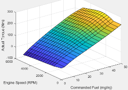
Power
| Input Command Setting | Description |
|---|---|
Fuel mass |
The engine brake torque lookup table is a function of commanded fuel mass and engine speed, = ƒ(F, N), where:
|
Torque | The engine brake torque lookup table is a function of target torque and engine speed, = ƒ(Ttarget, N), where:
|
Programmatic Use
To set the block parameter value programmatically, use
the set_param function.
To get the block parameter value
programmatically, use the get_param function.
| Parameter: | f_tbrake |
| Values: | M-by-N matrix |
| Data Types: | double |
Dependencies
To enable this parameter, clear Input engine temperature.
Click to plot table.
Dependencies
To enable this parameter, clear Input engine temperature.
| Input Command Setting | Description |
|---|---|
Fuel mass | The engine brake torque lookup table is a function of commanded fuel mass and engine speed, = ƒ(F, N, TempEng), where:
|
Torque | The engine brake torque lookup table is a function of target torque and engine speed, = ƒ(Ttarget, N, TempEng), where:
|
Programmatic Use
To set the block parameter value programmatically, use
the set_param function.
To get the block parameter value
programmatically, use the get_param function.
| Parameter: | f_tbrake_3d |
| Values: | M-by-N-by-L
array |
| Data Types: | double |
Dependencies
To enable this parameter, select Input engine temperature.
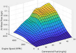
Air
| Input Command Setting | Description |
|---|---|
Fuel mass |
The air mass flow lookup table is a function of commanded fuel mass and engine speed, = ƒ(Fmax, N), where:
|
Torque | The air mass flow lookup table is a function of maximum torque and engine speed, = ƒ(Tmax, N), where:
|
Programmatic Use
To set the block parameter value programmatically, use
the set_param function.
To get the block parameter value
programmatically, use the get_param function.
| Parameter: | f_air |
| Values: | M-by-N matrix |
| Data Types: | double |
Dependencies
To enable this parameter, clear Input engine temperature.
Click to plot table.
Dependencies
To enable this parameter, clear Input engine temperature.
| Input Command Setting | Description |
|---|---|
Fuel mass | The air mass flow lookup table is a function of commanded fuel mass and engine speed, = ƒ(Fmax, N, TempEng), where:
|
Torque | The air mass flow lookup table is a function of maximum torque and engine speed, = ƒ(Tmax, N, TempEng), where:
|
Programmatic Use
To set the block parameter value programmatically, use
the set_param function.
To get the block parameter value
programmatically, use the get_param function.
| Parameter: | f_air_3d |
| Values: | M-by-N-by-L
array |
| Data Types: | double |
Dependencies
To enable this parameter, select Input engine temperature.
Fuel
| Input Command Setting | Description |
|---|---|
Fuel mass |
The engine fuel flow lookup table is a function of commanded fuel mass and engine speed, MassFlow= ƒ(F, N), where:
|
Torque | The engine fuel flow lookup table is a function of target torque and engine speed, MassFlow = ƒ(Ttarget, N), where:
|
Programmatic Use
To set the block parameter value programmatically, use
the set_param function.
To get the block parameter value
programmatically, use the get_param function.
| Parameter: | f_fuel |
| Values: | M-by-N matrix |
| Data Types: | double |
Dependencies
To enable this parameter, clear Input engine temperature.
Click to plot table.
Dependencies
To enable this parameter, clear Input engine temperature.
| Input Command Setting | Description |
|---|---|
Fuel mass | The engine fuel flow lookup table is a function of commanded fuel mass, engine speed, and engine temperature, MassFlow= ƒ(F, N, TempEng), where:
|
Torque | The engine fuel flow lookup table is a function of target torque and engine speed, and engine temperature, MassFlow = ƒ(Ttarget, N, TempEng), where:
|
Programmatic Use
To set the block parameter value programmatically, use
the set_param function.
To get the block parameter value
programmatically, use the get_param function.
| Parameter: | f_fuel_3d |
| Values: | M-by-N-by-L
array |
| Data Types: | double |
Dependencies
To enable this parameter, select Input engine temperature.
Temperature
| Input Command Setting | Description |
|---|---|
Fuel mass |
The engine exhaust temperature table is a function of commanded fuel mass and engine speed, Texh= ƒ(F, N), where:
|
Torque | The engine exhaust temperature table is a function of target torque and engine speed, Texh = ƒ(Ttarget, N), where:
|
Programmatic Use
To set the block parameter value programmatically, use
the set_param function.
To get the block parameter value
programmatically, use the get_param function.
| Parameter: | f_texh |
| Values: | M-by-N matrix |
| Data Types: | double |
Dependencies
To enable this parameter, clear Input engine temperature.
Click to plot table.
Dependencies
To enable this parameter, clear Input engine temperature.
| Input Command Setting | Description |
|---|---|
Fuel mass | The engine exhaust temperature table is a function of commanded fuel mass and engine speed, Texh= ƒ(F, N, TempEng), where:
|
Torque | The engine exhaust temperature table is a function of target torque and engine speed, Texh = ƒ(Ttarget, N, TempEng), where:
|
Programmatic Use
To set the block parameter value programmatically, use
the set_param function.
To get the block parameter value
programmatically, use the get_param function.
| Parameter: | f_texh_3d |
| Values: | M-by-N-by-L
array |
| Data Types: | double |
Dependencies
To enable this parameter, select Input engine temperature.
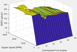
Efficiency
| Input Command Setting | Description |
|---|---|
Fuel mass |
The brake-specific fuel consumption (BSFC) efficiency is a function of commanded fuel mass and engine speed, BSFC= ƒ(F, N), where:
|
Torque | The brake-specific fuel consumption (BSFC) efficiency is a function of target torque and engine speed, BSFC = ƒ(Ttarget, N), where:
|
Programmatic Use
To set the block parameter value programmatically, use
the set_param function.
To get the block parameter value
programmatically, use the get_param function.
| Parameter: | f_eff |
| Values: | M-by-N matrix |
| Data Types: | double |
Dependencies
To enable this parameter, clear Input engine temperature.
Click to plot table.
Dependencies
To enable this parameter, clear Input engine temperature.
| Input Command Setting | Description |
|---|---|
Fuel mass | The brake-specific fuel consumption (BSFC) efficiency is a function of commanded fuel mass and engine speed, BSFC= ƒ(F, N, TempEng), where:
|
Torque | The brake-specific fuel consumption (BSFC) efficiency is a function of target torque and engine speed, BSFC = ƒ(Ttarget, N, TempEng), where:
|
Programmatic Use
To set the block parameter value programmatically, use
the set_param function.
To get the block parameter value
programmatically, use the get_param function.
| Parameter: | f_eff_3d |
| Values: | M-by-N-by-L
array |
| Data Types: | double |
Dependencies
To enable this parameter, select Input engine temperature.
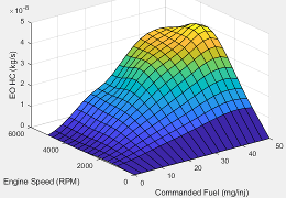
HC
| Input Command Setting | Description |
|---|---|
Fuel mass |
The engine-out hydrocarbon emissions are a function of commanded fuel mass and engine speed, EO HC= ƒ(F, N), where:
|
Torque | The engine-out hydrocarbon emissions are a function of target torque and engine speed, EO HC = ƒ(Ttarget, N), where:
|
Programmatic Use
To set the block parameter value programmatically, use
the set_param function.
To get the block parameter value
programmatically, use the get_param function.
| Parameter: | f_hc |
| Values: | M-by-N matrix |
| Data Types: | double |
Dependencies
To enable this parameter, clear Input engine temperature.
Click to plot table.
Dependencies
To enable this parameter, clear Input engine temperature.
| Input Command Setting | Description |
|---|---|
Fuel mass | The engine-out hydrocarbon emissions are a function of commanded fuel mass and engine speed, EO HC= ƒ(F, N, TempEng), where:
|
Torque | The engine-out hydrocarbon emissions are a function of target torque and engine speed, EO HC = ƒ(Ttarget, N, TempEng), where:
|
Programmatic Use
To set the block parameter value programmatically, use
the set_param function.
To get the block parameter value
programmatically, use the get_param function.
| Parameter: | f_hc_3d |
| Values: | M-by-N-by-L
array |
| Data Types: | double |
Dependencies
To enable this parameter, select Input engine temperature.
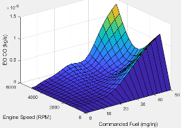
CO
| Input Command Setting | Description |
|---|---|
Fuel mass |
The engine-out carbon monoxide emissions are a function of commanded fuel mass and engine speed, EO CO= ƒ(F, N), where:
|
Torque | The engine-out carbon monoxide emissions are a function of target torque and engine speed, EO CO = ƒ(Ttarget, N), where:
|
Programmatic Use
To set the block parameter value programmatically, use
the set_param function.
To get the block parameter value
programmatically, use the get_param function.
| Parameter: | f_co |
| Values: | M-by-N matrix |
| Data Types: | double |
Dependencies
To enable this parameter, clear Input engine temperature.
Click to plot table.
Dependencies
To enable this parameter, clear Input engine temperature.
| Input Command Setting | Description |
|---|---|
Fuel mass | The engine-out carbon monoxide emissions are a function of commanded fuel mass and engine speed, EO CO= ƒ(F, N, TempEng), where:
|
Torque | The engine-out carbon monoxide emissions are a function of target torque and engine speed, EO CO = ƒ(Ttarget, N, TempEng), where:
|
Programmatic Use
To set the block parameter value programmatically, use
the set_param function.
To get the block parameter value
programmatically, use the get_param function.
| Parameter: | f_co_3d |
| Values: | M-by-N-by-L
array |
| Data Types: | double |
Dependencies
To enable this parameter, select Input engine temperature.
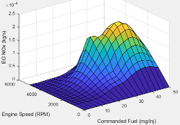
NOx
| Input Command Setting | Description |
|---|---|
Fuel mass |
The engine-out nitric oxide and nitrogen dioxide emissions are a function of commanded fuel mass and engine speed, EO NOx= ƒ(F, N), where:
|
Torque | The engine-out nitric oxide and nitrogen dioxide emissions are a function of target torque and engine speed, EO NOx = ƒ(Ttarget, N), where:
|
Programmatic Use
To set the block parameter value programmatically, use
the set_param function.
To get the block parameter value
programmatically, use the get_param function.
| Parameter: | f_nox |
| Values: | M-by-N matrix |
| Data Types: | double |
Dependencies
To enable this parameter, clear Input engine temperature.
Click to plot table.
Dependencies
To enable this parameter, clear Input engine temperature.
| Input Command Setting | Description |
|---|---|
Fuel mass | The engine-out nitric oxide and nitrogen dioxide emissions are a function of commanded fuel mass, engine speed, and engine temperature, EO NOx= ƒ(F, N, TempEng), where:
|
Torque | The engine-out nitric oxide and nitrogen dioxide emissions are a function of target torque, engine speed, and engine temperature, EO NOx = ƒ(Ttarget, N, TempEng), where:
|
Programmatic Use
To set the block parameter value programmatically, use
the set_param function.
To get the block parameter value
programmatically, use the get_param function.
| Parameter: | f_nox_3d |
| Values: | M-by-N-by-L
array |
| Data Types: | double |
Dependencies
To enable this parameter, select Input engine temperature.
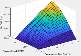
CO2
| Input Command Setting | Description |
|---|---|
Fuel mass |
The engine-out carbon dioxide emissions are a function of commanded fuel mass and engine speed, EO CO2= ƒ(F, N), where:
|
Torque | The engine-out carbon dioxide emissions are a function of target torque and engine speed, EO CO2 = ƒ(Ttarget, N), where:
|
Programmatic Use
To set the block parameter value programmatically, use
the set_param function.
To get the block parameter value
programmatically, use the get_param function.
| Parameter: | f_co2 |
| Values: | M-by-N matrix |
| Data Types: | double |
Dependencies
To enable this parameter, clear Input engine temperature.
Click to plot table.
Dependencies
To enable this parameter, clear Input engine temperature.
| Input Command Setting | Description |
|---|---|
Fuel mass | The engine-out carbon dioxide emissions are a function of commanded fuel mass, engine speed, and engine temperature, EO CO2= ƒ(F, N, TempEng), where:
|
Torque | The engine-out carbon dioxide emissions are a function of target torque, engine speed, and engine temperature, EO CO2 = ƒ(Ttarget, N, TempEng), where:
|
Programmatic Use
To set the block parameter value programmatically, use
the set_param function.
To get the block parameter value
programmatically, use the get_param function.
| Parameter: | f_co2_3d |
| Values: | M-by-N-by-L
array |
| Data Types: | double |
Dependencies
To enable this parameter, select Input engine temperature.
PM
| Input Command Setting | Description |
|---|---|
Fuel mass | The engine-out PM emissions are a function of commanded fuel mass and engine speed, where:
|
Torque | The engine-out PM emissions are a function of target torque and engine speed, EO PM = ƒ(Ttarget, N), where:
|
Programmatic Use
To set the block parameter value programmatically, use
the set_param function.
To get the block parameter value
programmatically, use the get_param function.
| Parameter: | f_pm |
| Values: | M-by-N matrix |
| Data Types: | double |
Dependencies
To enable this parameter, clear Input engine temperature.
Click to plot table.
Dependencies
To enable this parameter, clear Input engine temperature.
| Input Command Setting | Description |
|---|---|
Fuel mass | The engine-out PM emissions are a function of commanded fuel mass, engine speed, and engine temperature, where:
|
Torque | The engine-out PM emissions are a function of target torque, engine speed, and engine temperature, EO PM = ƒ(Ttarget, N, T), where:
|
Programmatic Use
To set the block parameter value programmatically, use
the set_param function.
To get the block parameter value
programmatically, use the get_param function.
| Parameter: | f_pm_3d |
| Values: | M-by-N-by-L
array |
| Data Types: | double |
Dependencies
To enable this parameter, select Input engine temperature.
Extended Capabilities
C/C++ Code Generation
Generate C and C++ code using Simulink® Coder™.
Version History
Introduced in R2017a
MATLAB Command
You clicked a link that corresponds to this MATLAB command:
Run the command by entering it in the MATLAB Command Window. Web browsers do not support MATLAB commands.
Website auswählen
Wählen Sie eine Website aus, um übersetzte Inhalte (sofern verfügbar) sowie lokale Veranstaltungen und Angebote anzuzeigen. Auf der Grundlage Ihres Standorts empfehlen wir Ihnen die folgende Auswahl: .
Sie können auch eine Website aus der folgenden Liste auswählen:
So erhalten Sie die bestmögliche Leistung auf der Website
Wählen Sie für die bestmögliche Website-Leistung die Website für China (auf Chinesisch oder Englisch). Andere landesspezifische Websites von MathWorks sind für Besuche von Ihrem Standort aus nicht optimiert.
Amerika
- América Latina (Español)
- Canada (English)
- United States (English)
Europa
- Belgium (English)
- Denmark (English)
- Deutschland (Deutsch)
- España (Español)
- Finland (English)
- France (Français)
- Ireland (English)
- Italia (Italiano)
- Luxembourg (English)
- Netherlands (English)
- Norway (English)
- Österreich (Deutsch)
- Portugal (English)
- Sweden (English)
- Switzerland
- United Kingdom (English)
