Modeling a Hydraulic Actuation System
Simscape Fluids™ is used to model a hydraulic actuation system. The hydraulic system includes a pump, four-way directional valve, and a double-acting hydraulic cylinder. The model is created by assembling the components into a physical schematic using Simscape™ physical connections. Simulation results are displayed in the Simscape Results Explorer, where the piston travel and actuation force are displayed. The system is then tested and connected to a Simscape Multibody™ model of a three-dimensional mechanical system. The 3D animation of the results shows how the system behaves with this more realistic load.
Recorded: 10 Jun 2016
In this demonstration, we're going to see how to model a hydraulic actuation system using Simscape Fluids. In our model of the hydraulic actuation system, the spool inside this valve controls the flow of pressure from a pump to either side of a hydraulic cylinder, which can extend and contract. A motor will drive the shaft of the pump controlling the speed, and a control system will adjust the position of the valve.
We will model this system within the Simulink® environment using Simscape Fluids. The model we build will look like this, and we'll see when we run our simulation that the piston goes over its entire range of travel. We will then connect this to a realistic model of a three-dimensional mechanical system to see how it behaves. I'll now switch over to the model so you can see how this is done.
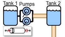
To start, we will enter the command ssc_new into the MATLAB® command window. This will open up a Simulink model with the settings recommended for Simscape models. The first thing that we'll need to add into our system is a pump. I will click on the diagram, and type in the word pump. Here I can see a list of the pumps I can choose from, and I will select a fixed displacement pump. I can specify the pump displacement here.
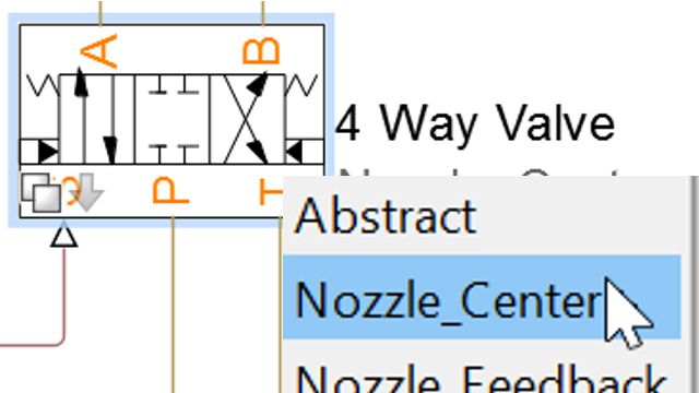
Our pump needs to draw fluid from a tank. We will use a hydraulic reference to represent that. I click and drag to create an ideal hydraulic connection, type in reference, and here I have an ideal hydraulic reference, which will represent our tank. To control the flow of fluid from the pump to the hydraulic actuator, we need a directional valve. I'll type in 4, and select from one of the directional valves that are available.
Double clicking on the block, I can go in and specify the different parameters. There are multiple parameterization options, so I can select the one appropriate for the datasheet that I have, or I can use one that's appropriate for measured data. I will increase the size of this valve to make it commensurate with the pump, and leave the rest of the settings as they are.
I will connect the P port of our valve to the high side of the pump. We need to limit the pressure coming from the pump. We will use a pressure relief valve to do that. I will right click and drag to create a hydraulic branch, and then type in relief valve to get the component. Double clicking on this block, I can also change these parameters. And I will adjust them to make them commensurate with the size of the pump and valve that we are working with. I'll connect the low side of the relief valve back to our tank. I'll also connect the low side of our hydraulic directional valve to our tank as well.
Next, we'll add our hydraulic actuator. I will click and drag to create a hydraulic connection, and type in cylinder. Here we can see the different cylinder components that we can use. I'll place this component in our network, create the additional hydraulic connection, and then double click on the block to set the parameters. We'll need to make this to actuator a bit bigger to handle our backhoe arm.
We'll change the piston stroke to match our design for our system. And we will change the hard stop parameters. These two mechanical connections represent the mechanical connections from our cylinder. We will connect this point to a point fixed in space. The other side is the rod, which is connected to the piston in the cylinder. We wish to have this act against a mechanical load. We will click and drag to create a mechanical connection, and then add a translational spring.
We want the cylinder to act against the spring damper, so we will click and drag, and also add a translational damper. And we'll attach this side to a point fixed in space. To specify the inertia of our load, we will click and drag, and add a mass block, and set the mass to be 100 kilograms.
Our physical system is complete, but we still need to specify the inputs to our system. One input is to our pump. We will click and drag to create a mechanical connection. We will insert an ideal angular velocity source in order to spin our pump at a fixed speed. The other side of this source we will attach to a point fixed in space. We will specify the speed of our pump using a constant block.
And we will specify it to speed at its rated speed of 188 radians per second. Because Simscape and Simscape Fluids use Solver technology above and beyond what is available in base Simulink, we will need access to additional settings. These we can access in the Solver configuration block. The remaining input to our system is the position of the spool and the valve. We will specify that using a Simulink signal. We need to specify the units of that signal, and we'll use this converter block to do it.
Here we can specify the units of the signal to be in meters, or the displacement of the spool inside the valve. To make the piston move over its entire range of travel, we will use a sine wave as an input. And we will specify the amplitude to be 3 millimeters. The last thing that we will do is specify the hydraulic fluids. We will click and drag to create a branch. And you insert a hydraulic fluid block. Here is where we can specify the type of fluid, and specify any of the other relevant parameters.
With this, our hydraulic network is complete. The last thing that we'll do is ensure that Simscape logging is enabled. Here in the Configuration panel under the Simscape pane, we can enable Simscape logging. We can also set other settings in order to configure how it is saved. Now we can run the simulation. And then right clicking on any block, we can access the Simscape Results Explorer.
Here we can see a tree browser that shows all of the simulation results. Because we right clicked on the translational spring, we can see different values, including the distance that the spring was compressed or how much the piston moved. We see that it moved over its entire range of travel of 0.5 meters. We can also see the amount of force that this actuation system can provide.
We can also explore hydraulic quantities, such as the pressure that the pump needs to deliver. We are satisfied with how our system behaves with this very simple load. Now we will add a more realistic load. We have built up a model of a three-dimensional mechanical system, the bucket and the arm, on our backhoe. Connect the mechanical connections here, and then connect the output of the subsystem we've put together to a Simulate Scope block.
Now when we run the simulation, we will see a 3D animation of the mechanical system. So we can see that our actuation system is moving the bucket back and forth. When we look on the scope, we can see that our system is moving over its entire range of travel. And when we go into the model of the Simscape multi-body system, we can also explore quantities using the Simscape Results Explorer. Here we can see the kinematic quantities of this specific joint. In this demonstration, we have seen how we can model a hydraulic actuation system using Simscape Fluids.
