Function Element
								Call
Libraries:
Simulink /
Ports & Subsystems
Description
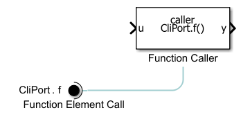
A Function Element Call block specifies which function call in a model is issued through the invoking function port. Use Function Element Call blocks to call port-scoped Simulink® functions that are defined in other models.
For example, the Function Element Call block labeled
CliPort.f specifies that the call of function,
f, is issued through the invoking function port,
CliPort.
Invoke Simulink Functions Using Function Element Call Blocks
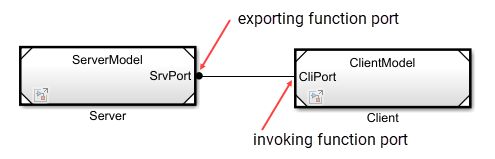
When you place a Function Element Call block at the root level of a referenced model, the corresponding Model block displays an invoking function port. An invoking function port is a port on a Model block that enables the model to issue function calls to a function provided by another referenced model.
For example, the Model block displays an invoking function port labeled
CliPort.
Note
A Function Element Call block can be placed anywhere in the current model hierarchy. Each Function Element Call block must correspond to a function caller, which specifies the function call associated with the invoking function port.
You can call a Simulink function in several ways, such as Function Caller block, a Chart (Stateflow), or a MATLAB Function block. For more information, see Call a Simulink Function from a Model.
Connecting this invoking function port to an exporting function port of another Model block enables a function in that model to be called. For more information, see the Model Client and Server Components Using Function Ports.
When to Use Function Element Call Blocks
Use Function Element Call blocks when:
You need a model to call a function defined in another referenced model.
You want to reuse function calls across multiple models without duplicating logic.
You have export-function models that require asynchronous function calls across model boundaries.
Examples
When you insert a Function Element Call block, the block label populates with default values. The label consists of two interactive text fields: the port name and the function element name. To change the name of the port associated with the block, edit the first text field in the label by clicking the text.
![]()
To allow multiple functions to be called through a port, create a
Function Element Call block for each function that you
want to include. In the block dialog box, click ![]() . Alternatively, hold
Ctrl while you drag an existing Function Element
Call block to a new location. Upon releasing the pointer, select
New Element.
. Alternatively, hold
Ctrl while you drag an existing Function Element
Call block to a new location. Upon releasing the pointer, select
New Element.
When multiple blocks are associated with the same port and you change the name of the port, the behavior depends on whether the new port name matches an existing port name.
If a port with the specified name exists, you assign the block and its element to the specified port. (since R2026a)
If a port with the specified name does not exist, you rename the port. The corresponding blocks update to reflect the new port name.
To create a port, hold Ctrl while you drag an existing Function Element Call block to a new location. Upon releasing the pointer, select New Port.
In the block dialog box:
Change port and function element names.
Reorder function elements by dragging an element into the list of elements.
Remove blocks associated with selected function elements by clicking
 .
.
To change the name of the function element associated with the block, edit the second text field in the label by clicking the text.
![]()
All function element names associated with the port must be unique. Each function element name should match the function name of one of the Simulink Function blocks to call through the port.
Use the function element name as the function name in the Function prototype parameter of the Function Caller block issuing function calls through the port, qualified by the port name. See Port name.
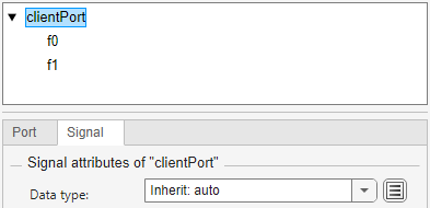
To associate the port with a service interface authored in System Composer™, specify the port data type.
Double-click a block associated with the port. Then, select the port name in the tree.
To display the data type, click ![]() .
.
Select a Simulink.ServiceBus object from the
Data type list or enter the
Simulink.ServiceBus object as Bus:
. The
ServiceInterfaceNameSimulink.ServiceBus object name now appears in
parentheses next to the port name.

You can associate a Simulink.ServiceBus object only with
the port as a whole, not with individual function elements within the
port.
Ports
Output
Parameters
To edit the element associated with a Function Element Call block, in the Simulink Editor, edit the block label.
To edit port attributes, use the Property Inspector. From the Simulink Toolstrip, on the Simulation tab, in the Prepare gallery, select Property Inspector.
Block Label
Specify a port name that is not already in use by another block or port within the model. The name appears as a port label on the parent Model block. The name also appears next to the block. Multiple blocks can access the same port.
Use the same port name to qualify, with dot notation, the function name in the Function prototype parameter of the Function Caller block issuing function calls through the port.
[OutArg1,OutArg2,...] = PortName.FunctionElementName(InArg1,InArg2,...)
Programmatic Use
To set the block parameter value programmatically, use
the set_param function.
| Parameter: | PortName |
| Values: | 'client' (default) | port name in quotes |
| Data Types: | char | string |
Example: set_param("mymodel/Function Element Call",
PortName="clientPort")
To specify the element that the block selects, in the Simulink Editor, edit the second text field of the block label.
Multiple blocks can access the same element.
Programmatic Use
To set the block parameter value programmatically, use
the set_param function.
| Parameter: | Element |
| Values: | 'f1' (default) | element path in quotes |
| Data Types: | char | string |
Example: set_param("mymodel/Function Element Call",
Element="f3")
Port Tab
To toggle whether the tabs are visible, click ![]() .
.
For information about the port name, see Port name.
Specify the order in which the port that corresponds to the block appears on the parent Model block.
If you add a block that creates another port, the port number is the next available number.
Deleting all blocks associated with a port deletes the port. The software renumbers other ports to be sequential and does not skip any numbers.
Specifying a port number that exceeds the number of ports creates a port for that number and for any skipped sequential numbers.
Programmatic Use
To set the block parameter value programmatically, use
the set_param function.
| Parameter: | Port |
| Values: | '1' (default) | real integer in quotes |
| Data Types: | char | string |
Example: set_param("mymodel/Function Element Call",
Port="5")
Signal Tab
To toggle whether the tabs are visible, click ![]() .
.
When you specify the port data type, a parenthetical appears next to the port name. To display the specified data type in full, click the attribute summary.
Before R2025a: To specify the port data type, pause on the port
name in the tree. Then, click ![]() . Alternatively, when available, click the
attribute summary.
. Alternatively, when available, click the
attribute summary.
The port data type can be inherited or specified.
Inherit: auto— Inherited data type.Bus: <object name>— Use the name of theSimulink.ServiceBusobject preceded byBus:. For example, specifyBus: myServiceInterface.ValueType: <object name>— Use the name of theSimulink.ValueTypeobject preceded byValueType:. For example, specifyValueType: windVelocity. The data type of theSimulink.ValueTypeobject must be aSimulink.ServiceBusobject.
Tips
To edit a
Simulink.ServiceBusorSimulink.ValueTypeobject, click .
.To create a
Simulink.ServiceBusorSimulink.ValueTypeobject, use the Architectural Data Editor or Interface Editor (System Composer).
Programmatic Use
To programmatically set the port data type, use the set_param
function. Specify the port as the model name, a forward slash,
and the port name.
| Parameter: | OutDataTypeStr |
| Values: | "Inherit: auto" (default) | "Bus: <object name>" | "ValueType: <object
name>" |
Example: set_param("mymodel/client",
OutDataTypeStr="Bus:
ServiceInterface")
Block Characteristics
Data Types |
|
Direct Feedthrough |
|
Multidimensional Signals |
|
Variable-Size Signals |
|
Zero-Crossing Detection |
|
Tips
Use the Filter box to specify a search term to use for filtering a long list of function elements. Do not enclose the search term in quotation marks. The filter does a partial string search and supports regular expressions. To use a regular expression character as a literal, include an escape character (
\). For example, to use a question mark, typefcn\?1. For more information, see Regular Expressions.To change the background color of a Function Element Call block, click
 and select a standard color or specify a
custom color. Alternatively, use the
and select a standard color or specify a
custom color. Alternatively, use the BackgroundColorblock property. For more information, see Programmatically Specify Block Parameters and Properties.
Extended Capabilities
Version History
Introduced in R2022aYou can now specify port attributes more easily.
To toggle the display of port attributes, click
 . Port attributes now appear on the
Port and Signal
tabs. The button replaces the button that appears
when you pause on the port name in a previous release.
. Port attributes now appear on the
Port and Signal
tabs. The button replaces the button that appears
when you pause on the port name in a previous release.To edit the port name, double-click the name of the port. Alternatively, on the Port tab, specify Port name.
To change block colors, click
and select a standard color or specify a
custom color.To create a
Simulink.Busobject using the Type Editor, on the Signal tab, click.