Ackermann Kinematic Model
Car-like vehicle motion using Ackermann kinematic model
Libraries:
Robotics System Toolbox /
Mobile Robot Algorithms
Description
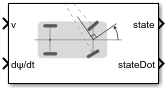
The Ackermann Kinematic Model block creates a car-like vehicle model that
uses Ackermann steering. This model represents a vehicle with two axles separated by the
distance, Wheel base. The
state of the vehicle is defined as a four-element vector, [x y θ ψ], with
an global xy-position, vehicle heading, θ, and steering
angle, ψ. The vehicle heading and xy-position are
defined at the center of the rear axle. Angles are specified in radians and the global
positions are specified in meters. The steering input for the vehicle is given as dψ/dt, in
radians per second.

Examples
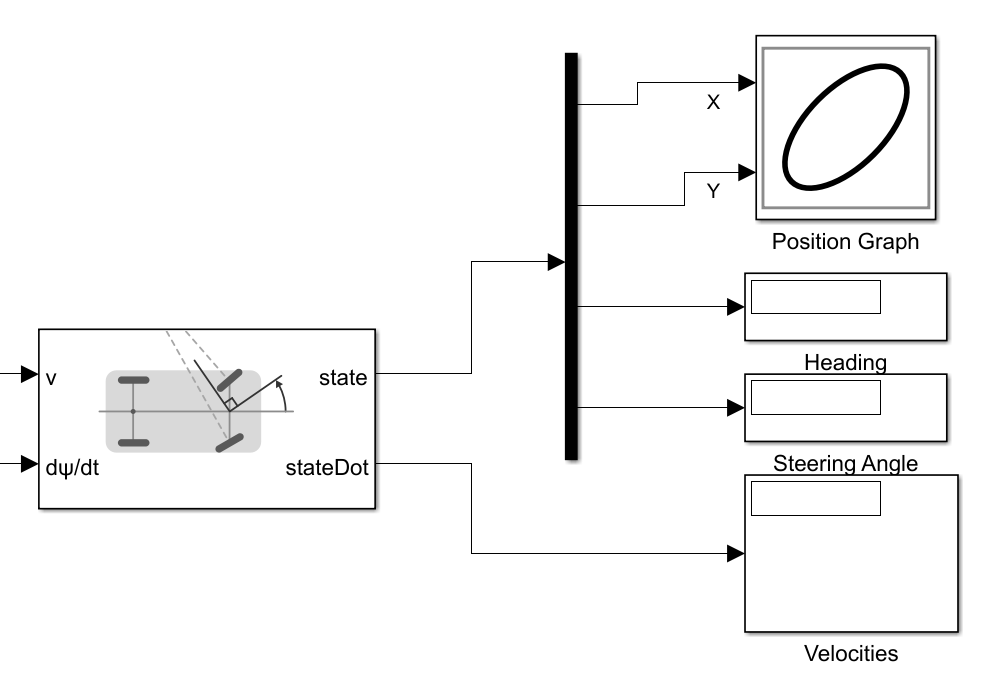
Plot Ackermann Drive Vehicle in Simulink
Plot the position of an Ackermann Kinematic Model block and change the vehicle velocity and steering angular velocity in real-time.
Ports
Input
Output
Parameters
References
[1] Lynch, Kevin M., and Frank C. Park. Modern Robotics: Mechanics, Planning, and Control. 1st ed. Cambridge, MA: Cambridge University Press, 2017.
Extended Capabilities
Version History
Introduced in R2019b