Differential Drive Kinematic Model
Compute vehicle motion using differential drive kinematic model
Libraries:
Robotics System Toolbox /
Mobile Robot Algorithms
Description
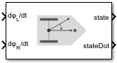
The Differential Drive Kinematic Model block creates a differential-drive
vehicle model to simulate simplified vehicle dynamics. This model approximates a vehicle with
a single fixed axle and wheels separated by a specified track width Track width.
Each of the wheels can be driven independently using speed inputs, dϕL/dt and dϕR/dt, for the left and right wheels respectively.
Vehicle speed and heading is defined from the axle center.

Examples
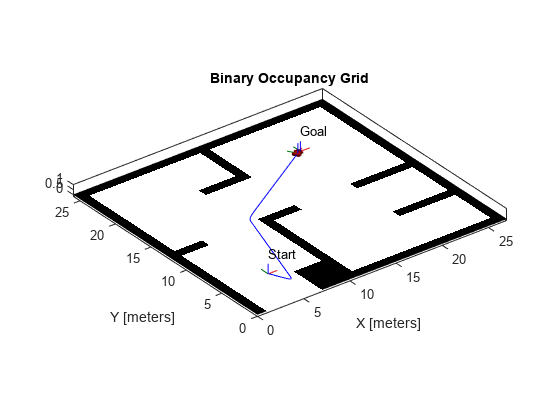
Plan Path for a Differential Drive Robot in Simulink
Navigate a differential drive robot on an obstacle-free path in Simulink® using probabilistic roadmap (PRM) planning and Pure Pursuit control.
Ports
Input
Output
Parameters
References
[1] Lynch, Kevin M., and Frank C. Park. Modern Robotics: Mechanics, Planning, and Control 1st ed. Cambridge, MA: Cambridge University Press, 2017.
Extended Capabilities
Version History
Introduced in R2019b