Main Content

phased.AngleDopplerScope

Angle-Doppler scope

Description

The phased.AngleDopplerScope 
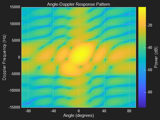
System object™ creates a scope for displaying an angle-Doppler response map. The map is a 2-D representation of response intensity as a function of angle and Doppler shift. You can input two types of data - in-phase and quadrature (I/Q) data and response data.

  • I/Q data – The data consists of I/Q samples at the same range from multiple sensors over all pulses or sweeps. The scope computes and displays the response map. To use I/Q data, set the IQDataInput property to true. In this mode, you can set the properties listed in Properties Applicable to I/Q Data.

  • Response data – The data consists of the angle-Doppler response itself. The scope only displays the angle-Doppler response map. You can obtain angle-Doppler response data from the phased.AngleDopplerResponse object. To display response data, set the IQDataInput property to false. In this mode, you can set the properties listed in Properties Applicable to Response Data.

To display an angle-Doppler response map using a scope,

  1. Create the phased.AngleDopplerScope object and set its properties.

  2. Call the object with arguments, as if it were a function.

To learn more about how System objects work, see What Are System Objects?

Creation

Description

scope = phased.AngleDopplerScope creates an angle-Doppler scope System object for displaying the angle-Doppler response map.

example

scope = phased.phased.AngleDopplerScope(Name,Value)creates an angle-Doppler scope with each specified property set to the specified value. You can specify additional name-value pair arguments in any order as (Name1,Value1,...,NameN,ValueN). Enclose property names in quotes. For example,

scope = phased.AngleDopplerScope('IQInputData',true, ...
      'NumAngleSamples',128,'NumDopplerSamples',64)
creates a scope object that computes and displays the angle-Doppler response at 128 angle values and 64 Doppler values from I/Q data input.

Properties

expand all

Unless otherwise indicated, properties are nontunable, which means you cannot change their values after calling the object. Objects lock when you call them, and the release function unlocks them.

If a property is tunable, you can change its value at any time.

For more information on changing property values, see System Design in MATLAB Using System Objects.

Display caption, specified as a character vector. The caption appears in the title bar of the window.

Example: 'Aircraft Angle-Doppler Response'

Tunable: Yes

Data Types: char

Location and size of the intensity scope window, specified as a 1-by-4 vector having the form [left bottom width height].

  • left and bottom specify the location of the bottom-left corner of the window.

  • width and height specify the width and height of the window.

Units are in pixels.

The default value of this property depends on the resolution of your display. By default, the window is positioned in the center of the screen, with a width and height of 800 and 450 pixels, respectively.

Example: [100 100 500 400]

Tunable: Yes

Data Types: double

Type of input data, specified as true or false. When true, the object assumes that the input consists of I/Q sample data and further processing is required in the range, angle, or Doppler domains. When false, the object assumes that the data is response data that has already been processed.

Data Types: logical

Response units, specified as 'db', 'magnitude', or 'power'.

Data Types: char

Angle-axis label, specified as a character vector.

Example: 'Angle Span (degrees)'

Tunable: Yes

Dependencies

To enable this property, set the IQDataInput to false.

Data Types: char

Doppler-axis label, specified as a character vector.

Example: 'Doppler Frequency (kHz)'

Tunable: Yes

Dependencies

To enable this property, set the IQDataInput to false.

Data Types: char

Sensor array, specified as a Phased Array System Toolbox array System object. See phased.ULA for the default values of a uniform linear array.

Example: phased.URA

Dependencies

To enable this property, set the IQDataInput to true.

Signal propagation speed, specified as a positive scalar. The default value of this property is the speed of light. See physconst. Units are in meters/second.

Example: 3e8

Dependencies

To enable this property, set the IQDataInput property to true.

Data Types: double

Operating frequency, specified as a positive scalar. Units are in Hz.

Dependencies

To enable this property, set the IQDataInput property to true.

Data Types: double

Pulse repetition frequency of input signal, specified as a positive scalar. Units are in Hz.

Example: 1.4e3

Dependencies

To enable this property, set the IQDataInput property to true.

Data Types: double

Elevation angle at which to calculate the response, specified as a scalar. The elevation angle must lie in the interval from –90° to 90°, inclusive. Units are in degrees.

Example: 45.0

Dependencies

To enable this property, set the IQDataInput property to true.

Data Types: double

Number of bins in the angle span at which to calculate the response, specified as a positive integer greater than two.

Example: 256

Dependencies

To enable this property, set the IQDataInput property to true.

Data Types: double

Number of bins in the Doppler domain used to calculate angle-Doppler response, specified as a positive integer greater than two.

Example: 512

Dependencies

To enable this property, set the IQDataInput property to true.

Data Types: double

Set this property to true to plot the angle-Doppler response at the normalized Doppler frequency. Set this property to false to plot the angle-Doppler response without normalizing the Doppler frequency.

Dependencies

To enable this property, set the IQDataInput property to true.

Data Types: logical

Doppler frequency units, specified as 'Hz', 'kHz', or 'MHz'.

Example: 'MHz'

Dependencies

To enable this property, set the IQDataInput property to true and the NormalizedDoppler property to false.

Data Types: char

Usage

Description

scope(X,Ang,Dop) displays an angle-Doppler response map for the response data, scope, for direction azimuth angles, Ang, and Doppler shifts, Dop. This syntax applies when you set the IQDataInput to false.

scope(X) computes and displays the angle-Doppler response map of the I/Q data X. This syntax applies when you set the IQDataInput property to true.

Input Arguments

expand all

Input data, specified as a real-valued P-by-Q or complex-valued P-by-Q matrix. The processing of the data depends on the value of the IQDataInput property.

  • When IQDataInput is true, x consists of I/Q samples at fixed range of pulses or sweeps from multiple elements or subarrays. P is the number of array elements. If SensorArray contains subarrays, P is the number of subarrays. Q is the number of pulses. The scope computes and displays the angle-Doppler response.

    When x is a column vector, L must be equal to an integer multiple of P.

  • When IQDataInput is false, x consists of real-valued angle-Doppler response data such as the data produced by phased.AngleDopplerResponse. P is the number of Doppler samples and Q is the number of angle samples. Each row represents a Doppler value corresponding to an element of Dop. Each column represents an angle value corresponding to an element of the Ang vector. The scope serves only as a display of the angle-Doppler response.

Azimuth angle grid values of response map, specified as a real-valued Q-by-1 column vector. Ang contains the angle values corresponding to the columns of X.

Dependencies

To enable this argument, set the IQInputData property to false.

Data Types: double

Doppler grid values of response map, specified as a real-valued P-by-1 column vector. Dop contains the Doppler values corresponding to the rows of X.

Dependencies

To enable this argument, set the IQInputData property to false.

Data Types: double

Object Functions

To use an object function, specify the System object as the first input argument. For example, to release system resources of a System object named obj, use this syntax:

release(obj)

expand all

showTurn on visibility of scopes
hideTurn off visibility of scope
isVisibleVisibility of scopes
stepRun System object algorithm
releaseRelease resources and allow changes to System object property values and input characteristics
resetReset internal states of System object

Examples

collapse all

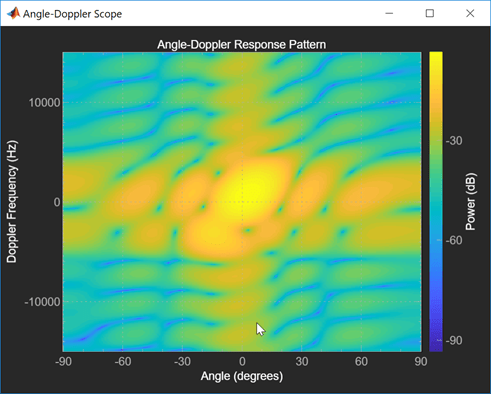
Calculate and visualize the angle-Doppler response at a single range cell of a collected data cube.

Load the I/Q data and analyze the 43th range cell.

load STAPExampleData;
x = shiftdim(STAPEx_ReceivePulse(43,:,:));

Create a scope object that processes I/Q data.

scope = phased.AngleDopplerScope( ...
    'IQDataInput', true, ...
    'Name','Angle-Doppler Scope', ...
    'Position',[560 375 560 420], ...
    'NormalizeDoppler',false, ...
    'ResponseUnits','db', ...
    'SensorArray',STAPEx_HArray, ...
    'OperatingFrequency',STAPEx_OperatingFrequency, ...
    'PropagationSpeed',STAPEx_PropagationSpeed, ...
    'PRF',STAPEx_PRF,'NumDopplerSamples',512);

Compute and visualize the angle-Doppler response.

scope(x)

More About

expand all

Version History

Introduced in R2019a