Implement PMSM Speed Control Using Active Disturbance Rejection Control
This example shows you how to implement active disturbance rejection control (ADRC) of the speed of a permanent magnet synchronous motor (PMSM) modeled in Simulink® using the Active Disturbance Rejection Control (Simulink Control Design) block. You can use the example to implement field-oriented control (FOC) using either a proportional integral (PI) or ADRC-based controller to run the motor in the speed control mode. Therefore, you can compare the performance of the PI and ADRC controllers.
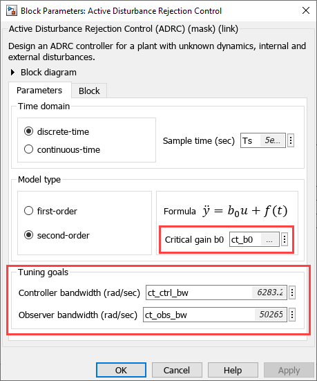
ADRC is a model-free control technique that you can use to design and implement controllers for plants that have unknown dynamics as well as internal and external disturbances. The ADRC block uses second-order approximation of the plant dynamics and disturbances modeled as an extended state of the plant and provides robust disturbance rejection without an overshoot.
The following equation defines the second order approximation of the control system that is used by the ADRC block:

Where:
 is the plant output.
 is the plant input.
 is the critical gain, which is the estimated gain that describes the plant response to an input .
 is the total disturbance in motor plant, which includes unknown dynamics and other disturbances.
The block uses an extended state observer to estimate and implements a disturbance rejection control that reduces the effect of the estimated disturbances on the known system dynamics. The ADRC controllers used in the example run in discrete-time domain.
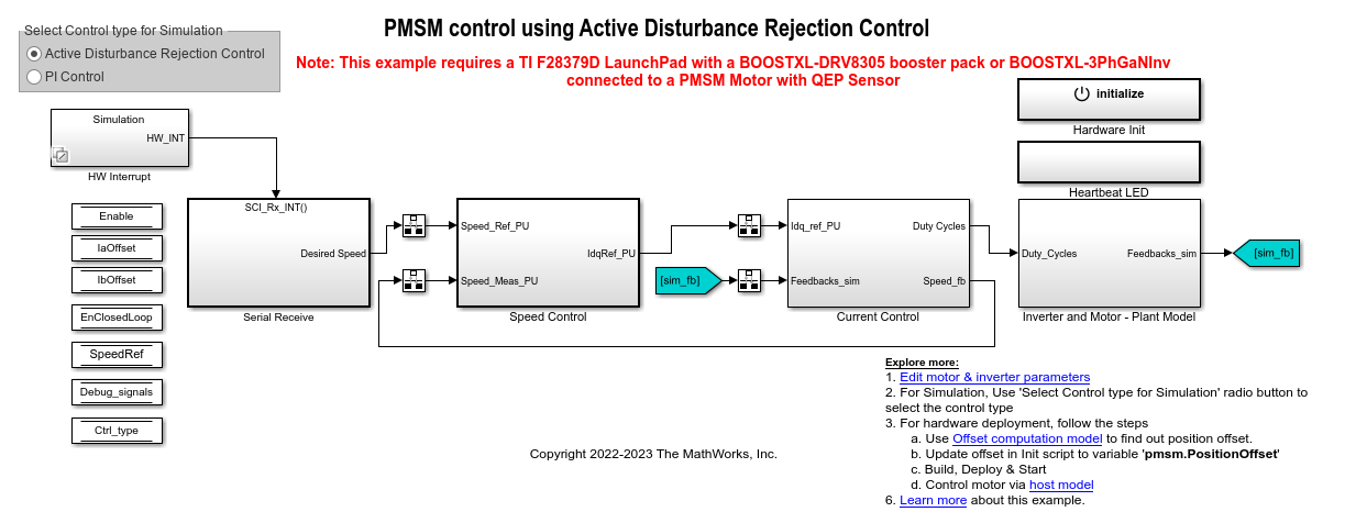
Model
This example includes the following target Simulink model:
mcb_pmsm_adrc_qep_f28379d
You can use this model for both simulation and hardware deployment.
Required MathWorks Products
To simulate model:
Motor Control Blockset™
Control System Toolbox™
Simulink Control Design™
To generate code and deploy model:
Motor Control Blockset
Control System Toolbox
Simulink Control Design
Embedded Coder®
C2000™ Microcontroller Blockset
Prerequisites
1. Obtain the motor parameters. The Simulink model uses default parameters that you can replace with values from either the motor datasheet or other sources.
However, if you have the motor control hardware, you can estimate the parameters for the motor that you want to use by using the Motor Control Blockset parameter estimation tool. For instructions, see . The parameter estimation tool updates the motorParam variable (in the MATLAB® workspace) with the estimated motor parameters.
2. Update motor parameters. If you obtain the motor parameters from the datasheet or from other sources, update the motor and inverter parameters in the model initialization script associated with the Simulink model. For instructions, see Estimate Motor Parameters Using Motor Control Blockset Parameter Estimation Tool.
If you use the parameter estimation tool, you can update the inverter parameters, but you do not need to update the motor parameters in the model initialization script. The script automatically extracts the motor parameters from the updated motorParam workspace variable.
Estimate Critical Gain for ADRC
To implement and use ADRC for your plant, it is essential that you compute the critical gain value of ADRC. The example includes a script that computes the critical gain value for a given set of controller and plant parameters using a simple experiment. The following steps describe the procedure to estimate the critical gain value using this script.
1. Open the target model mcb_pmsm_adrc_qep_f28379d included in the example.
2. Use the Select Control type for Simulation button to select PI Control. This enables the PI controllers included in the model.
3. Click Run on the Simulation tab, to begin simulation and run the PMSM plant model in closed-loop mode (using some PI controller gains).
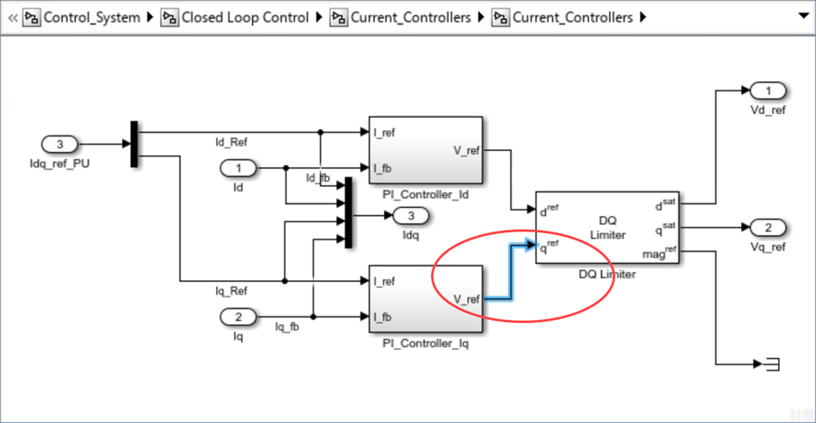
4. Open the subsystem mcb_pmsm_adrc_qep_f28379d/Current Control/Control_System/Closed Loop Control/Current_Controllers/Current_Controllers/.
5. Measure the q-axis voltage, Vq highlighted below to record the initial plant input,  .
.
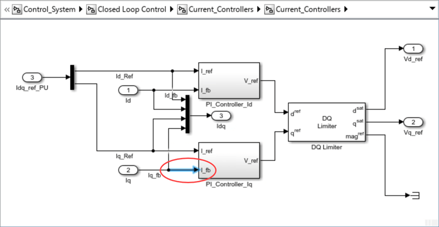
6. Measure the q-axis current, Iq feedback highlighted below to record the initial plant output,  .
.
7. Inject a step signal into the initial plant input signal (described in step 5) so that the plant input, rises from to  .
.
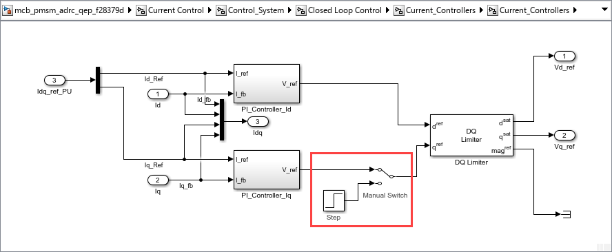
Note: The third screenshot shows an experimental modification that is not part of the actual model.
8. Measure the q-axis current, Iq feedback signal (described in step 6) and record the updated plant output,  . At the same time, measure the time taken (t) by the plant output to reach from .
9. Open the model initialization script mcb_pmsm_adrc_qep_f28379d_data.m and update the following variables:
◦ t — Update this variable with the time taken by the plant output to reach from .
◦ u — Update this variable with  .
.
◦ y — Update this variable with  .
.
The example script uses these variables to automatically compute and update the critical gain value of the Iq and Id ADRC controller, ct_b0:
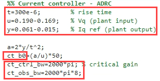
The ADRC block (in the Iq and Id current control loops) extracts the critical gain (ct_b0) as well as current controller bandwidth (ct_ctrl_bw) and observer bandwidth (ct_obs_bw) from the model initialization script.
10. Use similar steps to compute the critical gain, spd_b0, of the speed ADRC controller.
Note: Because multiple control loops execute simultaneously, this process can be challenging and might require considerable time and expertise.
Simulate Model
This example supports simulation. Follow these steps to simulate the model.
1. Open the target model included with this example.
2. Use the Select Control type for Simulation button to select the type of controller that you want to use:
◦ Active Disturbance Rejection Control — Select this option to enable ADRC controllers for speed and current control loops. To use this option, ensure that you follow the instructions in the Estimate Critical Gain for ADRC section to determine the critical gain value of ADRC.
◦ PI Control — Select this option to enable PI controllers for speed and current control loops.
3. Click Run on the Simulation tab to simulate the model.
4. Click Data Inspector in the Review Results section to view and analyze the simulation results.

Generate Code and Deploy Model to Target Hardware
This section shows how to generate code and run the FOC algorithm on the target hardware.
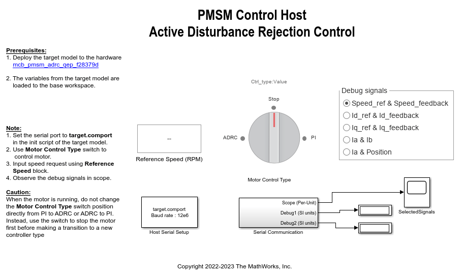
This example uses a host and a target model. The host model is a user interface to the controller hardware board. You can run the host model on the host computer. Before you run the host model on the host computer, deploy the target model to the controller hardware board. The host model uses serial communication to command the target Simulink model and run the motor in closed-loop control.
Required Hardware
The example supports this hardware configuration. You can also use the target model name to open the model from the MATLAB command prompt.
LAUNCHXL-F28379D controller + (BOOSTXL-DRV8305) inverter: mcb_pmsm_adrc_qep_f28379d
For connections related to this hardware configuration, see LAUNCHXL-F28069M and LAUNCHXL-F28379D Configurations.
Generate Code and Run Model on Target Hardware
1. Simulate the target model and observe the simulation results.
2. Complete the hardware connections.
3. The model automatically computes the ADC (or current) offset values. To disable this functionality (enabled by default), update the value 0 to the variable inverter.ADCOffsetCalibEnable in the model initialization script.
Alternatively, you can compute the ADC offset values and update it manually in the model initialization scripts. For instructions, see Run 3-Phase AC Motors in Open-Loop Control and Calibrate ADC Offset.
4. Compute the quadrature encoder index offset value and update it in the model initialization scripts associated with the target model. For instructions, see Quadrature Encoder Offset Calibration for PMSM.
Note: Verify the number of slits available in the quadrature encoder sensor attached to your motor. Check and update the variable pmsm.QEPSlits available in the model initialization script. This variable corresponds to the Encoder slits parameter of the Quadrature Encoder block. For more details about the Encoder slits and Encoder counts per slit parameters, see Quadrature Decoder.
5. Open the target model. If you want to change the default hardware configuration settings for the model, see Model Configuration Parameters.
6. Use the Select Control type for Simulation button to select the type of controller that you want to run on the hardware:
◦ Active Disturbance Rejection Control — Select this option to enable ADRC controllers for speed and current control loops. To use this option, ensure that you follow the instructions in the Estimate Critical Gain for ADRC section to determine the critical gain value of ADRC.
◦ PI Control — Select this option to enable PI controllers for speed and current control loops.
7. Load a sample program to CPU2 of the LAUNCHXL-F28379D board to ensure that CPU2 is not mistakenly configured to use the board peripherals intended for CPU1. For example, load the program that operates the CPU2 blue LED by using GPIO31 (c28379D_cpu2_blink.slx). For more information about the sample program or model, see the Task 2 - Create, Configure and Run the Model for TI Delfino F28379D LaunchPad (Dual Core) section in Getting Started with Texas Instruments C2000 Microcontroller Blockset (C2000 Microcontroller Blockset).
8. Click Build, Deploy & Start on the Hardware tab to deploy the target model to the hardware. Verify that the MATLAB base workspace reflects the variables from the target model.
9. Click the mcb_pmsm_adrc_host_model_f28379d.slx host model hyperlink in the target model to open the associated host model.
For details about serial communication between the host and target models, see Host-Target Communication.
10. In the model initialization script associated with the target model, specify the communication port using the variable target.comport. The example uses this variable to update the Port parameter of the Host Serial Setup, Host Serial Receive, and Host Serial Transmit blocks available in the host model.
11. Based on the Select Control type for Simulation button setting on the target model, set the Motor Control Type switch to either PI (to enable the PI Controller) or to ADRC (to enable the ADRC controller).
12. Update the reference speed value in the Reference Speed (RPM) field in the host model. We recommend that you enter lower speeds initially during motor start up and gradually increase the speed later.
13. Click Run on the Simulation tab to run the host model.
14. Use the Debug signals section to select the debug signals that you want to monitor. Observe the debug signals from the Serial Communication subsystem, in the SelectedSignals scope of the host model.
Caution: When the motor is running, do not use the Motor Control Type to switch directly from PI to ADRC or ADRC to PI controller. Instead, use the switch to stop the motor before making a transition to a new controller type.