Model Configuration Parameters
Update the configuration parameters for a Simulink® model that you create, before simulating or deploying the model to the controller.
In the Simulink window, click Hardware Settings in the HARDWARE tab to open the Configuration Parameters dialog box and select the target hardware in the Hardware board field.

Solver Configuration
In the Solver tab of the Configuration Parameters dialog box,
for a fixed-step discrete solver, type auto in the
Fixed-step size (fundamental sample time) field.

ADC Interface Configuration
If you connect analog inputs (current or voltage sensors) to the hardware board, configure the related ADC parameters in the Configuration Parameters dialog box by using these steps:
Open the Hardware Implementation tab.
Set the ADC clock prescaler and check the ADC clock frequency. Ensure that the displayed ADC clock frequency is less than the maximum value specified in the device datasheet.
This example shows the ADC configuration for LAUNCHXL-F28379D board. The maximum operating frequency of ADCCLK for TMS320F28379D targets is 50 MHz.

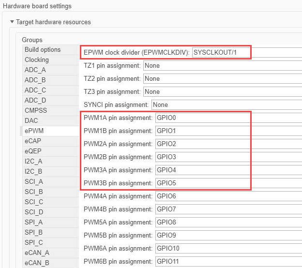
PWM Interface Configuration
If you connect PWM outputs from target device to the inverter, configure the related PWM parameters in the Configuration Parameters dialog box by using the following steps:
Open the Hardware Implementation tab.
Set the ePWM clock divider to SYSCLKOUT/1.
Update the following PWM pin assignment fields.
| ePWM pin settings | Property |
|---|---|
PWM1A pin assignment | Gate pulse for Phase-A high-side transistor |
PWM1B pin assignment | Gate pulse for Phase-A low-side transistor |
PWM2A pin assignment | Gate pulse for Phase-B high-side transistor |
PWM2B pin assignment | Gate pulse for Phase-B low-side transistor |
PWM3A pin assignment | Gate pulse for Phase-C high-side transistor |
PWM3B pin assignment | Gate pulse for Phase-C low-side transistor |
Hall Sensor Interface Configuration
If you connect a Hall sensor to the hardware board, configure the related parameters in the Configuration Parameters dialog box by using the following steps:
Open the Hardware Implementation tab.
Select the eCAP group under Hardware board settings > Target hardware resources.
Update the following ECAP pin assignment fields:
| ECAP pin assignment field | Field value |
|---|---|
| Hall A |
| Hall B |
| Hall C |
The following example shows the eCAP configuration for a Hall sensor connected to DRV8312 board with a F28069 Piccolo MCU control card:

Quadrature Encoder Interface Configuration
If you connect a Quadrature Encoder sensor to the hardware board, configure the related parameters in the Configuration Parameters dialog box by using the following steps:
Open the Hardware Implementation tab.
Select the eQEP group under Hardware board settings > Target hardware resources.
Update the following EQEP pin assignment fields:
| EQEP pin assignment field | Property |
|---|---|
| Quadrature Encoder Channel A |
| Quadrature Encoder Channel B |
| Quadrature Encoder Index |
The following example shows the eQEP configuration for a quadrature encoder sensor connected to a LAUNCHXL-F28379D board:

Serial Communication Interface Configuration
If you are generating code and using serial communication between host and target Simulink models, configure the related parameters in the Configuration Parameters dialog box by using the following steps:
Open the Hardware Implementation tab.
Select the SCI_A group under Hardware board settings > Target hardware resources.
Update the following SCI_A settings:
SCI_A settings Property Suspension modeSerial suspension mode Number of stop bitsStop bits Parity modeParity Character length bitsData bits Desired baud rate in bits/secSerial communication baud rate Pin assignment(Tx)Output pin for Serial Transmit
Pin
                                        assignment(Rx)
Input pin for Serial Receive
For example, use the following SCI_A configuration for a Hall sensor connected to a F28379D LaunchPad board:
