Estimate Control Gains and Tune Control Parameters
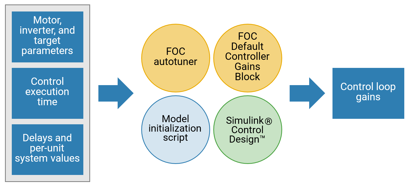
Tune speed and torque control loops that are part of the Field-Oriented Control (FOC) algorithm. You can choose from these methods to compute the control loop gains from the system or block transfer functions that are available for the motors, inverter, and controller:
Use the Field Oriented Control Autotuner block.
Use the FOC Default Controller Gains block.
Use Simulink® Control Design™.
Use the model initialization script.
To compute control loop gains, each method requires the following control parameters:
Motor, inverter, and target parameters
Control execution time
Delays and per-unit system values
Field-Oriented Control Autotuner
The Field-Oriented Control Autotuner block of Motor Control Blockset™ enables you to automatically tune the PID control loops in your Field-Oriented Control (FOC) application in real time. You can automatically tune the PID controllers associated with the following loops (for more details, see How to Use Field Oriented Control Autotuner Block):
Direct-axis (d-axis) current loop
Quadrature-axis (q-axis) current loop
Speed loop
For each loop that the block tunes, the Field-Oriented Control Autotuner block performs autotuning experiment in a closed-loop manner without using a parametric model associated with that loop. The block enables you to specify the order in which the block tunes the control loops. When the tuning experiment runs for one loop, the block has no effect on the other loops. For more details about FOC autotuner, see Field Oriented Control Autotuner and Tune PI Controllers Using Field Oriented Control Autotuner.
FOC Default Controller Gains Block
The FOC Default Controller Gains block of Motor Control Blockset enables you to integrate control gain calculations into the controller code. Using the library block, you can determine controller gains during runtime without recompiling the code when switching between different motor setups.
Simulink Control Design
Simulink Control Design enables you to design and analyze the control systems modeled in Simulink. You can automatically tune the arbitrary single-input, single-output (SISO) and multiple-input, multiple-output (MIMO) control architectures, including the PID controllers. You can deploy PID autotuning to the embedded software to automatically compute the PID gains in real time.
You can find the operating points and compute the exact linearizations of the Simulink models at different operating conditions. Simulink Control Design provides tools that let you compute the simulation-based frequency responses without modifying your model. For details, see Offline Frequency Response Estimation (Simulink Control Design).
Model Initialization Script
You can use the initialization scripts included with Motor Control Blockset examples to initialize the control parameters needed to estimate control gains. For a list of initialization functions, see Initialize Control Parameters. For a list of control gain estimation functions, see Compute Control Gains and Perform Control Analysis.
For example, for a PMSM that is connected to a quadrature encoder, these steps describe the procedure to initialize control parameters from the system details by using the initialization script:
Open an example that uses an initialization script. For instance:
openExample('mcb/FOCQepExample')Open the initialization script (
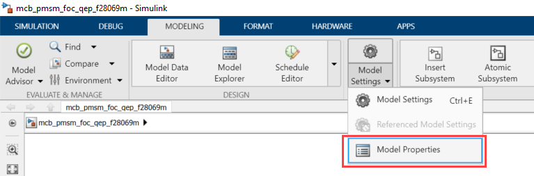
.m) file of the example in MATLAB®. To find the associated script file name:Open the example model. Select Modeling > Model Settings > Model Properties. The Model Properties Dialog box opens.
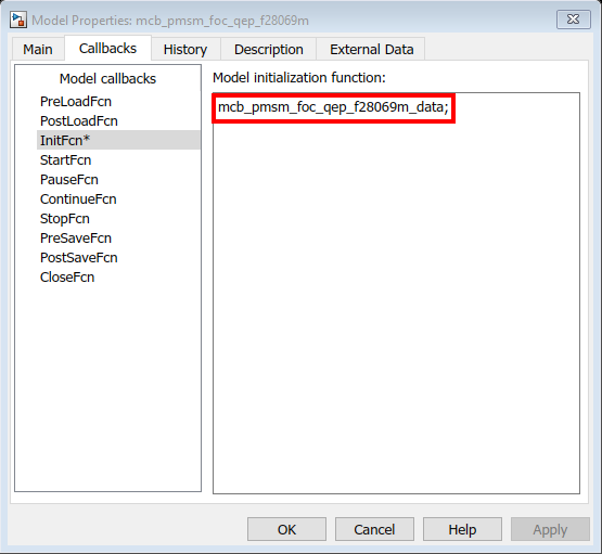
In the Model Properties dialog box, navigate to the Callbacks tab > InitFcn field. This field contains the name of the script that Simulink executes at the beginning of model compilation.
This figure shows the contents of the
mcb_pmsm_foc_qep_f28069m_data.minitialization script.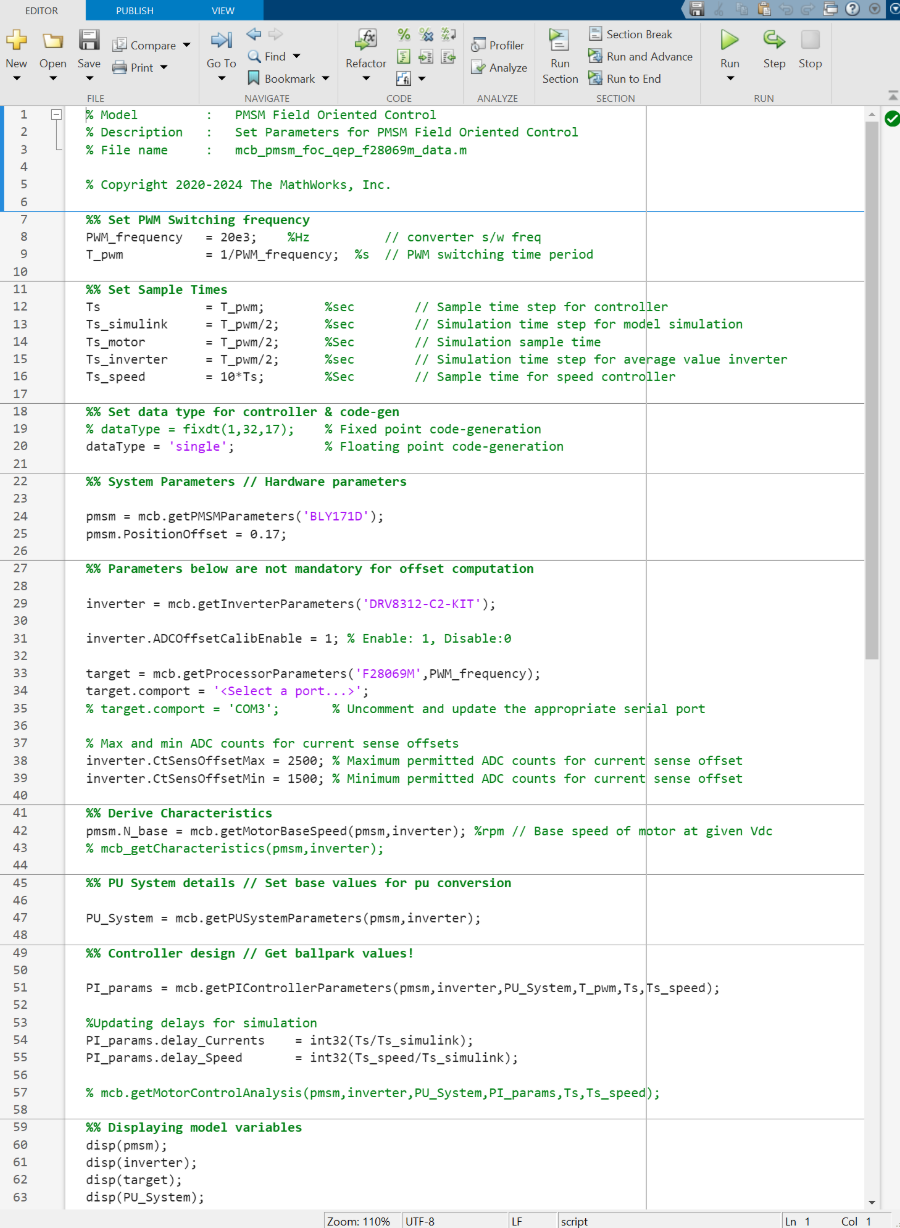
Use the Workspace to edit the control variables values. For example, to update Stator resistance (
Rs), use the variablepmsmto add the parameter value to theRsfield.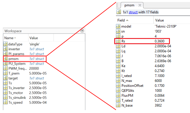
Initialize Control Parameters
The model initialization script associated with a target model calls these functions and sets up the workspace with the necessary variables.
| Function Called By Model Initialization Script | Description |
|---|---|
mcb.getPMSMParameters | Input to the function is the make and manufacturer name of the PMSM (for example, BLY171D). The function
returns a structure named It also computes the permanent magnet flux and rated torque for the selected motor. If you specify the name of a
new motor, the function returns a This function also loads the
structure |
mcb.getACIMParameters | Input to the function is the make and manufacturer name of the ACIM (for example, EM_Synergy). The
function returns a structure named If you specify the name
of a new motor, the function returns an
This
function also loads the structure
|
mcb.getInverterParameters | Input to the function is the make and manufacturer name of the inverter (for example, BoostXL-DRV8305). The function returns a
structure named The function also computes the inverter resistance for the selected inverter. If you specify the name of a
new inverter, the function returns an
|
mcb.getProcessorParameters | Inputs to the function are processor type (for example, F28379D) and the Pulse-Width Modulation (PWM) switching frequency. The function returns a structure
named The function also computes the PWM counter period that is a parameter for the ePWM block in the target model. |
mcb.getPUSystemParameters | Inputs to the function are motor and inverter parameters. The function sets the base values of the per-unit system for voltage, current, speed, torque, and power. The function returns a structure named
|
mcb.getSISystemParameters | Inputs to the function are motor and inverter parameters. The function sets the base values of the SI system for voltage, current, speed, torque, and power. The function returns a structure named
|
mcb.updateInverterParameters | Inputs to the function are motor and inverter parameters. The function updates the inverter parameters based on the selected hardware and motor. |
Note
For predefined processors and drivers, the model initialization script uses the default values.
Compute Control Gains and Perform Control Analysis
The model initialization script uses these functions to estimate the control gains needed to implement field-oriented control.
| Computed Control Parameter Category | Function | Functionality |
|---|---|---|
| Base speed of the motor | mcb.getMotorBaseSpeed | Calculates the base speed of PMSM at the rated voltage and rated load. Base speed is the maximum motor speed at the rated voltage and rated load, outside the field-weakening region. |
| Motor characteristics for the given motor and inverter | mcb.PMSMCharacteristics | Obtain these drive characteristics of a PMSM motor.
|
mcb.ACIMCharacteristics | Obtain these motor characteristics of an induction motor.
Obtain these drive characteristics of an induction motor.
| |
| Control algorithm parameters | mcb.getPIControllerParameters | Compute the gains for these PI controllers:
To compute PI controller gains for a PMSM,
use |
mcb.calcFOCGains | Compute the gains and transfer functions for these PI controllers:
| |
| Control analysis for the motor and inverter you are using | mcb.getMotorControlAnalysis | Performs frequency domain analysis for the computed gains of PI controllers used in the field-oriented motor control system. Note This function requires Control System Toolbox™. |