Explore Slices from 3-D Image Volume with Anisotropic Voxel Spacing
This example shows how to display slices from an anisotropic 3-D MRI volume. In an anisotropic image volume, the spacing between voxels, or volume pixels, varies between spatial dimensions. For example, if a 1-by-1-by-1 voxel maps to a 1-by-1-by-2 mm region in world coordinates, the voxel spacing is anisotropic. By default, Image Processing Toolbox™ functions display images in voxel units, and assume that spacing is uniform in world coordinates. As a result, anisotropic volumes can appear distorted.
In this example, you apply two approaches for displaying slices along each dimension without distortions:
Apply Display Settings — Set name-value arguments in display functions to customize the display without modifying the underlying image.
Transform Image Data — Apply resampling and geometric transformations to the underlying image data before displaying it.
Medical Imaging Toolbox™ extends the functionality of Image Processing Toolbox™ to automatically manage spatial referencing between voxels, world coordinates, and anatomical axes. To learn more, see Choose Approach for Medical Image Visualization (Medical Imaging Toolbox).
Load MRI Data
Load an MRI data set that contains a numeric array D and a grayscale colormap map. The numeric array contains the MRI image data. The voxel spacing is anisotropic, with transverse slices that are 2.5 times thicker in world coordinates than slices along the coronal and sagittal axes. You can use the colormap to display the volume with sufficient contrast. Remove singleton dimensions by using the squeeze function.
load mri
DTransverse = squeeze(D);
Apply Display Settings
In this section, you use display function name-value arguments to display the MRI volume without distortion. These name-value arguments update only the aspect ratio of the display, and do not modify the underlying image data. Adjusting only the display is beneficial when you do not want to modify the raw intensity values of the data using interpolation. A limitation of this approach is that you must set the name-value arguments each time you display the volume. Additionally, some functions, such as montage, do not have arguments for scaling anisotropic volumes.
Display Orthogonal Slices
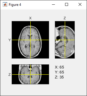
Display orthogonal slice planes by using the orthosliceViewer object. Specify the ScaleFactors name-value argument to apply a 2.5 scale factor to the third dimension. Each slice view includes a crosshair that you can use to navigate the volume. To navigate slices, pause on one of the crosshair axes until the cursor changes to the fleur shape, ![]() , and then click and drag to a new position. The other slice views update automatically.
, and then click and drag to a new position. The other slice views update automatically.
figure
orthosliceViewer(DTransverse,ScaleFactors=[1 1 2.5]);

Display Stack of Slices
Display a scrollable stack of slices by using the sliceViewer object. By default, sliceViewer displays slices along the third dimension. In this example, voxel spacing in the first two dimensions is equal, so the 2-D slices do not appear distorted.
sliceViewer(DTransverse,Parent=figure);
title("Transverse Slices")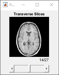
Change the slice direction and apply scale factors using the SliceDirection and ScaleFactors name-value arguments, respectively. Display a stack of sagittal slices by specifying the slice direction as "X" with a 2.5 scale factor for the third dimension.
sliceViewer(DTransverse,SliceDirection="X",ScaleFactors=[1 1 2.5],Parent=figure);
title("Sagittal Slices")

Display Slices as 3-D Object
Display the slices in 3-D by using the volshow function with the SlicePlanes rendering style. To display the anisotropic voxels without distortion, specify the Transformation name-value argument as an affinetform3d object that scales the volume by a factor of 2.5 in the third dimension. Click and drag a slice to navigate between slices along that axis. To rotate the volume to a desired orientation, click any empty space in the figure window and drag. To snap the view to a particular slice plane, click the X, Y, or Z label on the axis indicator in the bottom-left corner of the viewer.
sx = 1;
sy = 1;
sz = 2.5;
A = [sx 0 0 0; 0 sy 0 0; 0 0 sz 0; 0 0 0 1];
tform = affinetform3d(A);

vol = volshow(DTransverse,renderingStyle="SlicePlanes",Transformation=tform);
You can also view the volume as a 3-D object with advanced lighting using the cinematic rendering style.
vol = volshow(DTransverse,renderingStyle="CinematicRendering",Transformation=tform);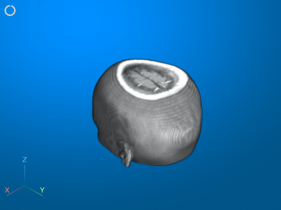
Explore Slices and 3-D Volume Using Volume Viewer
Explore image volumes interactively using the Volume Viewer app. Launch the app by using the volumeViewer function. To correctly display the anisotropic voxels, specify the ScaleFactors name-value argument.
volumeViewer(DTransverse,ScaleFactors=[1 1 2.5])
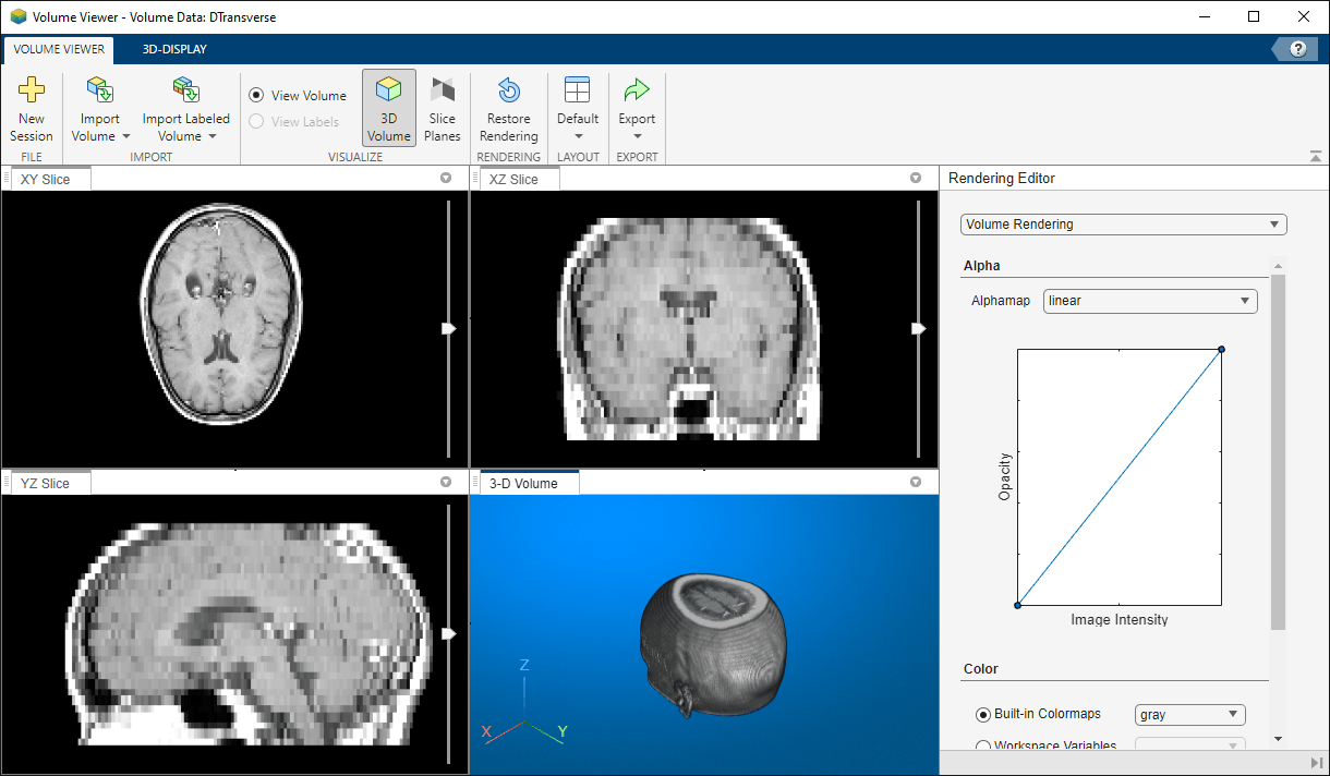
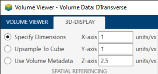
You can also specify scale factors in the app. In the 3D-Display tab of the app toolstrip, under Spatial Referencing, enter scale factor values for each axis. When you enter values, the option to the left of the values automatically changes to Specify Dimensions.
Transform Image Data
In this section, you use resampling and geometric transformation to modify an image volume before displaying it. Resampling interpolates the anisotropic voxel grid to an isotropic grid that displays the images without scaling distortions. You can also rotate the volume or apply other geometric transformations to orient the volume to a desired display convention. A benefit of this approach is that you do not need to specify name-value arguments each time you display the volume. Additionally, this approach enables you to use functions such as montage, which do not support changing the default scaling or slice direction using name-value arguments.
Resample Volume to Isotropic Voxel Spacing
Resample the original volume to an isotropic voxel grid by using the imresize3 function. Calculate the target number of slices for the isotropic volume using a 2.5 scale factor.
numSlices = round(2.5*size(DTransverse,3));
DTransverseIsotropic = imresize3(DTransverse,[128 128 numSlices]);
You can accurately display the resampled volume using display functions without applying scale factors. Display the resampled volume using orthoSliceViewer without the ScaleFactors name-value argument.
figure
orthosliceViewer(DTransverseIsotropic);
Display Montage of Oriented Slices
The montage function displays image volumes as a stack of slices along the third dimension. This section shows how to modify the image data to view slices along all three dimensions in the expected orientation for each anatomical plane.
Display the slices of the resampled transverse volume. Apply the colormap map to display the image with sufficient contrast.
figure
montage(DTransverseIsotropic,map)

title("Transverse Slices")To view the volume as a stack of sagittal slices, reorder the dimensions of DTransverseIsotropic.
DSagittal = permute(DTransverseIsotropic,[1 3 2]);
Rotate the volume to match the expected orientation of a sagittal slice, with the top of the head at the top of the image and the anterior side of the head on the left side of the image.
DSagittalRotated = imrotate3(DSagittal,90,[0 0 1],"cubic");Display the sagittal slices as a montage. Include the colormap to set the display range. Use the Indices name-value argument to display slices 20 to 100, to exclude empty slices.
figure
montage(DSagittalRotated,map,Indices=20:100)
title("Sagittal Slices")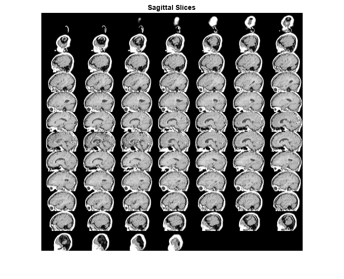
To view the volume as a stack of coronal slices, reorder the dimensions of DTransverseIsotropic.
DCoronal = permute(DTransverseIsotropic,[2 3 1]);
Rotate the volume to match the expected orientation for a coronal slice, with the top of the head at the top of the image and the left side of the head on the left side of the image.
DCoronalRotated = imrotate3(DCoronal,90,[0 0 1],"cubic");Display the coronal slices as a montage. Include the colormap to set the display range. Use the Indices name-value argument to display slices 17 to 127, to exclude empty slices.
figure
montage(DCoronalRotated,map,Indices=17:127)
title("Coronal Slices")
See Also
Volume Viewer | Medical Image
Labeler (Medical Imaging Toolbox) | sliceViewer | orthosliceViewer | volshow | imresize3 | imrotate3