Overview of Filter Banks
A digital filter bank is an array of digital bandpass filters with either a common input or a common output. A filter bank can be an analysis filter bank with a series of analysis filters, or a synthesis filter bank with a series of synthesis filters. The analysis filter bank separates the input broadband signal x[n] into multiple components, each carrying a subband of the original signal. The synthesis filter bank merges these subbands into a single broadband signal, a reconstructed version of the original input signal.

Analysis Filter Bank (Channelizer)
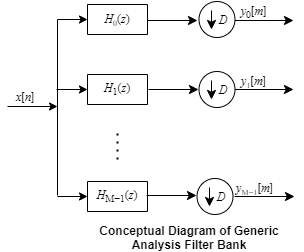
The generic analysis filter bank, also known as the channelizer, consists of a series of parallel bandpass filters that split an input broadband signal, x[n], into a series of narrow subbands. Each bandpass filter retains a different portion of the input signal. After the bandwidth is reduced by one of the bandpass filters, the signal is downsampled to a lower sample rate commensurate with the new bandwidth.

The first branch in the filter bank contains a lowpass filter, H0(z), which acts as a prototype filter. The remaining filters H1(z) through HM−1(z) are modulated versions of this filter. These modulated versions can be rearranged in terms of a complex exponential (modulation factor) followed by the prototype lowpass filter H0(z).

y1[m], y2[m], …, yM-1[m] are narrow subband signals translated into baseband.
For more details on this structure, see Analysis Filter Bank.
This filter bank can be implemented efficiently using a polyphase structure. For
more details on the polyphase structure and how it is implemented in the dsp.Channelizer object and the Channelizer block, see Channelizer Algorithm. The chief
advantage of this polyphase implementation is that you can downsample the signal
prior to filtering, thereby allowing you to filter the signal at a lower sample
rate.
Synthesis Filter Bank (Channel synthesizer)
The synthesis filter bank, also known as the channel synthesizer, consists of a set of parallel bandpass filters that merge multiple input narrowband signals, y0[m], y1[m], y2[m], … , yM-1[m] into a single broadband signal, v[n]. The input narrowband signals are in the baseband. Each narrowband signal is interpolated to a higher sample rate by using the upsampler, and then filtered by the lowpass filter. A complex exponential that follows the lowpass filter centers the baseband signal around wk, where and .
![Conceptual diagram of synthesis filter bank. Contains M branches. Each branch contains an upsampler, followed by a lowpass filter followed by a complex exponential. The output from each branch is added to form the reconstructed signal v[n].](synthesis_bank.png)
This filter bank is implemented efficiently using the polyphase structure
described in Channel Synthesizer Algorithm.
The dsp.ChannelSynthesizer object and the
Channel Synthesizer block in DSP System Toolbox™ use this implementation.
Two-Channel (Halfband) Filter Bank
Two-channel filter bank is a special case of the generic M-channel filter bank, where the number of filter branches is two.
The DFT matrix of the analysis portion looks like the following matrix.
The first row adds the two polyphase branches to give the lowpass subband output. The second row subtracts the two polyphase branches to give the highpass subband output. The halfband decimator objects and blocks in DSP System Toolbox implement their algorithm as shown in this diagram. A0(z) and A1(z) are the allpass polyphase components. This structure is the analysis portion of the two-channel halfband filter bank. Due to the halfband nature of the filters, one of the branches in this polyphase structure becomes a pure delay component.

For more details on this structure and its derivation, see Polyphase Implementation under Algorithms on these reference pages.
| Two-Channel Filter Bank | MATLAB® | Simulink® |
|---|---|---|
| Analysis portion using FIR halfband filter | dsp.FIRHalfbandDecimator | FIR Halfband Decimator |
| Analysis portion using IIR halfband filter | dsp.IIRHalfbandDecimator | IIR Halfband Decimator |
Similarly, the halfband interpolator objects and blocks in DSP System Toolbox implement their algorithm as shown in this diagram. This structure is the synthesis portion of the two-channel halfband filter bank. Due to the halfband nature of the filters, one of the branches in this polyphase structure becomes a pure delay component.

For more details on this structure and its derivation, see Polyphase Implementation under Algorithms on these reference pages.
| Two-Channel Filter Bank | MATLAB | Simulink |
|---|---|---|
| Synthesis portion using FIR halfband filter | dsp.FIRHalfbandInterpolator | FIR Halfband Interpolator |
| Synthesis portion using IIR halfband filter | dsp.IIRHalfbandInterpolator | IIR Halfband Interpolator |
The other two-channel filter bank features that DSP System Toolbox offers let you specify the lowpass and highpass filter coefficients. These features can customize the partitioning of the broadband signal. For an example, see Reconstruction Through Two-Channel Filter Banks.
| Two-Channel Filter Bank | MATLAB | Simulink |
|---|---|---|
| Analysis filter bank | dsp.SubbandAnalysisFilter | Two-Channel Analysis Subband Filter |
| Synthesis filter bank | dsp.SubbandSynthesisFilter | Two-Channel Synthesis Subband Filter |
You can use the subband analysis and synthesis filter banks as basic units and create multilevel filter banks. For more details, see Multilevel Filter Banks.
See Also
Topics
- Two-Channel Filter Bank Using Halfband Decimators and Halfband Interpolators
- Channelize and Synthesize Sine Wave in MATLAB
- Synthesize and Channelize Audio in Simulink
- Reconstruction Through Two-Channel Filter Banks
- Multilevel Filter Banks