Code Mappings Editor
Map AUTOSAR elements for code generation
Description
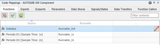
The Code Mappings editor is a graphical interface for mapping AUTOSAR elements for code generation. Map Simulink® model elements such as inports, outports, and entry-point functions to AUTOSAR component elements such as receiver ports, sender ports, and runnables.
Using a tabbed table format, the Code Mappings editor displays model inports, outports, and other model elements relevant to your AUTOSAR platform. Use this view to map model elements to AUTOSAR component elements from a Simulink model perspective. The mappings that you configure are reflected in generated AUTOSAR-compliant C or C++ code and exported ARXML descriptions.
For more information, see:

Open the Code Mappings Editor
If your model already has a mapped AUTOSAR software component, in the model window, do one of the following:
From the Apps tab, open the AUTOSAR Component Designer app.
Click the perspective control in the lower-right corner and select Code.
The model opens in the AUTOSAR code perspective, which includes the Code Mappings editor.
If your model does not have a mapped AUTOSAR component, in the model window, do one of the following:
Use the AUTOSAR Component Quick Start.
On the Modeling tab, select Model Settings. In the Configuration Parameters dialog box, Code Generation pane, set the system target file to either
autosar.tlcorautosar_adaptive.tlc. Click OK.On the Apps tab, click AUTOSAR Component Designer. The AUTOSAR Component Quick Start opens.
Work through the component quick-start procedure and click Finish.
For an Embedded Coder® model, you can use the Embedded Coder Quick Start.
With the Embedded Coder app open, on the C Code tab, select Quick Start. The Embedded Coder Quick Start opens.
As you work through the quick-start procedure, in the Output window, select output option C code compliant with AUTOSAR or C++ code compliant with AUTOSAR Adaptive Platform.
Click Finish.
The model opens in the AUTOSAR code perspective, which includes the Code Mappings editor.
Examples
Related Examples
- Map AUTOSAR Elements for Code Generation
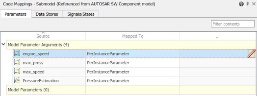
- Map Calibration Data for Submodels Referenced from AUTOSAR Component Models
- Configure AUTOSAR Elements and Properties
- Map AUTOSAR Adaptive Elements for Code Generation
- Configure AUTOSAR Adaptive Elements and Properties
- Configure and Map AUTOSAR Component Programmatically
Tips
The Code Mappings editor provides in-canvas access to AUTOSAR mapping information, with batch editing, element filtering, easy navigation to model elements and AUTOSAR properties, and model element traceability. As you progressively configure the model representation of the AUTOSAR component, you can apply these Code Mappings editor controls:
Filter contents field – Selectively display some elements, while omitting others, in the current view.
AUTOSAR Dictionary button
 – Switch from the Code Mappings editor view
of a Simulink element to the AUTOSAR Dictionary view of the corresponding
AUTOSAR element.
– Switch from the Code Mappings editor view
of a Simulink element to the AUTOSAR Dictionary view of the corresponding
AUTOSAR element.Validate button
 – Validate the AUTOSAR component
configuration.
– Validate the AUTOSAR component
configuration.Update button
 – Update the Simulink to AUTOSAR mapping of the model to reflect model changes, such as
adding, changing, or removing Simulink entry-point functions, parameters, signals, data transfers, or
function callers.
– Update the Simulink to AUTOSAR mapping of the model to reflect model changes, such as
adding, changing, or removing Simulink entry-point functions, parameters, signals, data transfers, or
function callers.Edit icon
 – Open a properties dialog box to view and
modify additional AUTOSAR code and calibration attributes for the
currently-selected element.
– Open a properties dialog box to view and
modify additional AUTOSAR code and calibration attributes for the
currently-selected element.
Version History
Introduced in R2018a