Map Calibration Data for Submodels Referenced from AUTOSAR Component Models
In a Simulink® implementation of an AUTOSAR design, model references allow you to organize and manage large or numerous AUTOSAR components hierarchically. You can define an algorithm in a submodel and reference it repeatedly. Referenced models compile independently from the models that use them, allowing modular development, reuse and sharing of algorithms across multiple components and designs, and incremental code generation.
For any model in an AUTOSAR model reference hierarchy, you can configure the model data for run-time calibration. In submodels referenced from AUTOSAR software component models, you can use the Code Mappings editor or equivalent functions to map parameters, data stores, signals, and states. Submodel mapped internal data can be used in memory sections, and is available for software-in-the-loop (SIL) and processor-in-the-loop (PIL) testing from the top model or calibration in the AUTOSAR run-time environment.
Submodel Data Mapping Workflow
To map Simulink submodel elements to AUTOSAR software component elements:
Configure the submodel as a model referenced from an AUTOSAR software component model. Use the AUTOSAR Component Quick Start or the AUTOSAR function
autosar.api.create.In the AUTOSAR Code perspective, use the Code Mappings editor to configure the submodel internal data.
To generate C code and AUTOSAR XML (ARXML) files that support run-time calibration of the submodel internal data, open and build the component model that references the submodel.
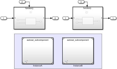
For this example, select a model that is referenced from an AUTOSAR software component model. This example uses autosar_subcomponent, which is referenced twice in the AUTOSAR component model autosar_component. These models are associated with the example script Configure Subcomponent Data for AUTOSAR Calibration and Measurement.
Open the submodel in a separate model window. In the model window, from the Apps tab, open the AUTOSAR Component Designer app. If the submodel is mapped to an AUTOSAR component, it opens in the AUTOSAR Code perspective.
If the submodel is unmapped, the AUTOSAR Component Quick Start opens. Work through the quick-start procedure. In the Set Component pane, select Model referenced from AUTOSAR software component model.
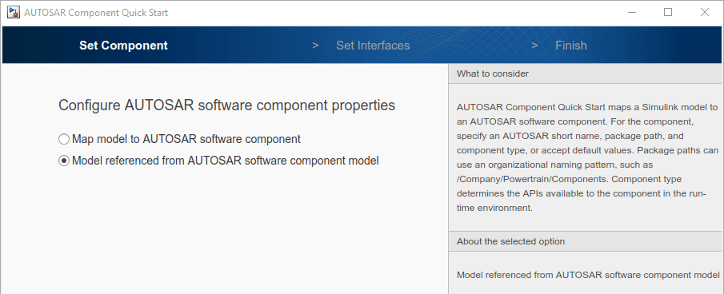
When you complete the quick-start procedure and click Finish, the submodel opens in the AUTOSAR Code perspective.
To add shared definitions of software address methods to use with the submodel, use the
AUTOSAR importer function updateModel and specify the name of an AUTOSAR XML (ARXML) file
containing the shared definitions. For example:
ar = arxml.importer("SwAddrMethods.arxml");
updateModel(ar,hModel);
In the AUTOSAR Code perspective, use the Code Mappings editor to:
Map individual parameters to
PerInstanceParameters.If block signals that must be mapped to AUTOSAR variables are not displayed in the Code Mappings editor, select the signals and add them to the mapping table.
Map individual signals, states, and data stores to
ArTypedPerInstanceMemorys.After setting the Mapped To property for a parameter, signal, state, or data store, click the
 icon to view and modify other AUTOSAR code and calibration attributes.
If you have Simulink Coder™ and Embedded Coder® software, you can build the component model that references the submodel. When you build, the exported ARXML files and generated C code support run-time calibration of the submodel internal data. The ARXML files exported for the top model include descriptions of the submodel parameters, signals, states, and data stores, as well as software address methods used in the submodel. The generated C code references the submodel internal data. The model build also generates macros that provide access to the submodel data for SIL and PIL testing and calibration in the AUTOSAR run-time environment. For more information, see Generate Submodel Data Macros for Verification and Deployment.
To programmatically configure a submodel as a model referenced from an AUTOSAR software component model, use the AUTOSAR function autosar.api.create and specify the name-value pair argument "ReferencedFromComponentModel",true. For example:
hModel = "autosar_subcomponent";
open_system(hModel);
autosar.api.create(hModel,"default","ReferencedFromComponentModel",true);
Map Submodel Parameters to AUTOSAR Component Parameters
On the Parameters tab of the Code Mappings editor, you can map Simulink submodel parameters to AUTOSAR per-instance parameters for AUTOSAR run-time calibration. Examples of model workspace parameters you can map include:
Simulink parameter objects
Simulink lookup table objects
Simulink breakpoint objects
By mapping lookup table and breakpoint objects to AUTOSAR internal calibration parameters, you can model AUTOSAR parameters for integrated and distributed lookups. For more information, see Configure Lookup Tables for AUTOSAR Calibration and Measurement.
After creating model workspace parameters in your model, for example, using Model Explorer, open the Code Mappings editor and select the Parameters tab. Select Simulink model workspace parameters and map them to AUTOSAR component per-instance parameters.
For more information, see Configure Model Workspace Parameters as AUTOSAR Per-Instance Parameters.
The Parameters tab lists each Simulink model workspace parameter that you can map to an AUTOSAR parameter. You can:
Map a parameter by selecting it and then selecting a menu value for an AUTOSAR parameter type:
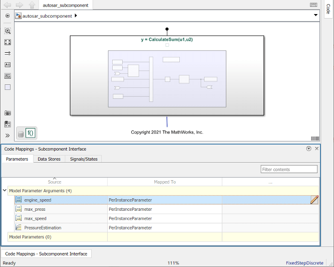
PerInstanceParameterorAuto. To accept software mapping defaults, specifyAuto.For example, here is the Parameters tab for submodel
autosar_subcomponent. AUTOSAR software component modelautosar_componentcontains two instances ofautosar_subcomponent.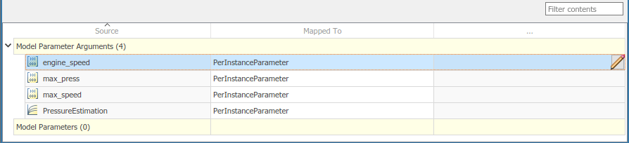
If you select parameter type
PerInstanceParameter, click the icon to view and modify other AUTOSAR code and calibration attributes for the parameter.Attribute Purpose ShortName Specify a short name for the AUTOSAR parameter. If unspecified, ARXML export generates a short name based on the Simulink parameter name. Short names are not supported for port-based parameters (
PortParameter) since the port name can be used across multiple applications.SwAddrMethod Select a SwAddrMethodname from the names listed as valid for the AUTOSAR parameter. For example, the submodelautosar_subcomponentdefines CALIB_32. Code generation uses theSwAddrMethodname to group AUTOSAR parameters in a memory section for access by calibration and measurement tools. For more information, see Configure SwAddrMethod.SwCalibrationAccess Specify how calibration and measurement tools can access the AUTOSAR parameter. Valid access values include ReadOnly,ReadWrite, andNotAccessible. For more information, see Configure SwCalibrationAccess.DisplayFormat Specify a display format for the AUTOSAR parameter. For example, %5.1f. AUTOSAR display format specifications control the width and precision display for calibration and measurement data. For more information, see Configure DisplayFormat.LongName Specify a description for the AUTOSAR parameter.
Map Submodel Data Stores to AUTOSAR Variables
On the Data Stores tab of the Code Mappings editor, you can map Simulink submodel data store memory blocks to AUTOSAR-typed per-instance memory elements for AUTOSAR run-time calibration.
After creating data store memory blocks in your model, open the Code Mappings editor and select the Data Stores tab. Select data stores and map them to AUTOSAR-typed per-instance memory elements. For more information, see Configure AUTOSAR Per-Instance Memory.
The Data Stores tab lists each Simulink data store that you can map to an AUTOSAR variable. You can:
Map a data store by selecting the data store, and then selecting a menu value for an AUTOSAR variable type:
ArTypedPerInstanceMemoryorAuto. To accept software mapping defaults, specifyAuto.For example, here is the Local Data Stores tab for submodel
autosar_subcomponent. AUTOSAR software component modelautosar_componentcontains two instances ofautosar_subcomponent.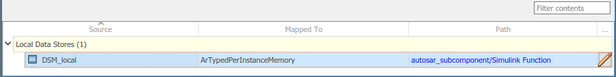
If you select variable type
ArTypedPerInstanceMemory, click the icon to view and modify other AUTOSAR code and calibration attributes for the variable.Attribute Purpose ShortName Specify a short name for the AUTOSAR variable. For example, dsmsig. If unspecified, ARXML export generates a short name.NeedsNVRAMAccess Select or clear the option to indicate whether the AUTOSAR variable needs access to nonvolatile RAM on a processor. To configure the per-instance memory to be a mirror block for a specific NVRAM block, select the option. SwAddrMethod Select a SwAddrMethodname from the names listed as valid for the AUTOSAR variable. For example, the submodelautosar_subcomponentdefines VAR_INIT_32. Code generation uses theSwAddrMethodname to group AUTOSAR variables in a memory section for access by calibration and measurement tools. For more information, see Configure SwAddrMethod.RestoreAtStart Select or clear the option to indicate if the state should be read out at startup. StoreAtShutdown Select or clear the option to indicate if the state written away at shutdown. SwCalibrationAccess Specify how calibration and measurement tools can access the AUTOSAR variable. Valid access values include ReadOnly,ReadWrite, andNotAccessible. For more information, see Configure SwCalibrationAccess.DisplayFormat Specify a display format for the AUTOSAR variable. For example, %5d. AUTOSAR display format specifications control the width and precision display for calibration and measurement data. For more information, see Configure DisplayFormat.LongName Specify a description for the AUTOSAR variable.
Map Submodel Signals and States to AUTOSAR Variables
On the Signals/States tab of the Code Mappings editor, you can map Simulink submodel block signals and states to AUTOSAR-typed per-instance memory elements for AUTOSAR run-time calibration.
In the Code Mappings editor, Simulink block states that correspond to state owner blocks are available for mapping.
To make Simulink block signals available for mapping, use a Code Mappings editor button or a model cue:
In the model canvas, select one or more signals. Open the Code Mappings editor, Signals/States tab, and click the Add button
 .
.In the model canvas, select a signal. Place your cursor over the displayed ellipsis and select model cue Add selected signals to code mappings.
Alternatively, call MATLAB® function addSignal.
After selectively adding block signals to AUTOSAR signal mapping, open the Code Mappings editor and select the Signals/States tab. Select block signals and states and map them to AUTOSAR-typed per-instance memory elements. For more information, see Configure AUTOSAR Per-Instance Memory.
The Signals/States tab lists each Simulink block signal and state that you can map to an AUTOSAR variable. You can:
Map a Simulink signal or state by selecting the signal or state, and then selecting a menu value for an AUTOSAR variable type:
ArTypedPerInstanceMemoryorAuto. To accept software mapping defaults, specifyAuto.For example, here is the Signals/States tab for submodel
autosar_subcomponent. AUTOSAR software component modelautosar_componentcontains two instances ofautosar_subcomponent.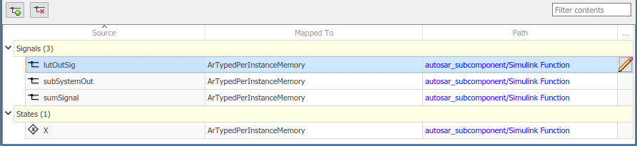
If you select variable type
ArTypedPerInstanceMemory, click the icon to view and modify other AUTOSAR code and calibration attributes for the variable.Attribute Purpose ShortName Specify a short name for the AUTOSAR variable. For example,
lutsig. If unspecified, ARXML export generates a short name.For signals, the auto-generated short name can differ from the signal name.
For states, the auto-generated short name is based on the state name if one exists. If the state is unnamed, the generated name can differ from the block name.
SwAddrMethod Select a SwAddrMethodname from the names listed as valid for the AUTOSAR variable. For example, the submodelautosar_subcomponentdefines VAR_INIT_32. Code generation uses theSwAddrMethodname to group AUTOSAR variables in a memory section for access by calibration and measurement tools. For more information, see Configure SwAddrMethod.SwCalibrationAccess Specify how calibration and measurement tools can access the AUTOSAR variable. Valid access values include ReadOnly,ReadWrite, andNotAccessible. For more information, see Configure SwCalibrationAccess.DisplayFormat Specify a display format for the AUTOSAR variable. For example, %1d. AUTOSAR display format specifications control the width and precision display for calibration and measurement data. For more information, see Configure DisplayFormat.LongName Specify a description for the AUTOSAR variable.
To remove Simulink block signals from AUTOSAR signal mapping, use a Code Mappings editor button or a model cue:
In the model canvas or on the Signals/States tab, select one or more signals. On the Signals/States tab, click the Remove button
 .
.In the model canvas, select a signal. Place your cursor over the displayed ellipsis and select model cue Remove selected signals from code mappings.
Alternatively, call MATLAB function removeSignal.
Generate Submodel Data Macros for Verification and Deployment
When you build an AUTOSAR software component model that references a submodel, the exported ARXML files and generated C code support run-time calibration of the submodel internal data.
The ARXML files exported for the top model include descriptions of the submodel parameters, signals, states, and data stores, as well as software address methods used in the submodel.
The generated C code references the submodel internal data.
The model build also generates macros that provide access to the submodel mapped internal data for SIL and PIL testing from the referencing component model, and calibration in the AUTOSAR run-time environment. If an AUTOSAR component model build encompasses a referenced model with mapped internal data, the generated submodel header file references these macros:
INCLUDE_RTE_HEADER — Flag indicating whether to include an RTE component header.
RTE_COMPONENT_HEADER — Name of a header file containing definitions for submodel internal parameters, signals, states, and data stores.
For example, if you build AUTOSAR software component model autosar_component, which contains two instances of autosar_subcomponent, the generated file autosar_subcomponent.h contains this code.
#ifdef INCLUDE_RTE_HEADER
#include RTE_COMPONENT_HEADER
#endif
If you run top-model SIL or PIL testing from an AUTOSAR software component model that references a mapped submodel, the SIL or PIL model build automatically picks up the submodel internal data definitions.
When you integrate the generated code into an AUTOSAR run-time environment, you must configure the INCLUDE_RTE_HEADER and RTE_COMPONENT_HEADER macros to include the submodel internal data definitions.
See Also
autosar.api.create | Code Mappings Editor
Topics
- Configure Subcomponent Data for AUTOSAR Calibration and Measurement
- Configure Model Workspace Parameters as AUTOSAR Per-Instance Parameters
- Configure AUTOSAR Per-Instance Memory
- Map AUTOSAR Elements for Code Generation
- Integrate Generated Code for Multi-Instance Software Components
- AUTOSAR Component Configuration