Configure AUTOSAR Elements and Properties
In Simulink®, you can use the AUTOSAR Dictionary and the Code Mappings editor to graphically configure an AUTOSAR software component and map Simulink model elements to AUTOSAR component elements. For more information, see AUTOSAR Component Configuration.
Use the AUTOSAR Dictionary to configure AUTOSAR elements from an AUTOSAR perspective. Using a tree format, the AUTOSAR Dictionary displays a mapped AUTOSAR component and its elements, communication interfaces, computation methods, software address methods, and XML options. Use the tree to select AUTOSAR elements and configure their properties. The properties that you modify are reflected in exported ARXML descriptions and potentially in generated AUTOSAR-compliant C code.
AUTOSAR Elements Configuration Workflow
To configure AUTOSAR component elements for the Classic Platform in Simulink:
Open a model for which AUTOSAR system target file
autosar.tlcis selected.Create or open a mapped view of the AUTOSAR model. In the model window, do one of the following:
From the Apps tab, open the AUTOSAR Component Designer app.
Click the perspective control in the lower-right corner and select Code.
If the model has not yet been mapped to an AUTOSAR software component, the AUTOSAR Component Quick Start opens. Work through the quick-start procedure and click Finish. For more information, see Create Mapped AUTOSAR Component with Quick Start.
The model opens in the AUTOSAR Code perspective. This perspective displays the model and directly below the model, the Code Mappings editor.
This example uses the example model
autosar_swc_slfcns, which you can open by running the following command in the MATLAB® command window:openExample("autosar_swc_slfcns");Open the AUTOSAR Dictionary. Either click the AUTOSAR Dictionary button
 in the Code Mappings editor or, on the AUTOSAR tab, select Code Interface > AUTOSAR Dictionary.
To configure AUTOSAR elements and properties, use the AUTOSAR Dictionary tree to add and remove elements, or select elements to view and modify their properties. Use the Filter Contents field (where available) to selectively display some elements, while omitting others, in the current view.
After configuring AUTOSAR elements and properties, open the Code Mappings editor. Use the Code Mappings tabs to map Simulink elements to new or modified AUTOSAR elements.
Click the Validate button
 to validate the AUTOSAR component configuration. If errors are reported, address them and then retry validation.
Configure AUTOSAR Atomic Software Components
AUTOSAR atomic software components contain AUTOSAR elements defined in the AUTOSAR standard, such as ports, runnables, inter-runnable variables (IRVs), and parameters. In the AUTOSAR Dictionary, component elements appear in a tree format under the component that owns them. To access component elements and their properties, you expand the component name.

To configure AUTOSAR atomic software component elements and properties:
Open a model for which a mapped AUTOSAR software component has been created. For more information, see Component Creation.
From the Apps tab, open the AUTOSAR Component Designer app.
Open the AUTOSAR Dictionary. Either click the AUTOSAR Dictionary button
in the Code Mappings editor or, on the AUTOSAR tab, select Code Interface > AUTOSAR Dictionary.In the leftmost pane of the AUTOSAR Dictionary, under AUTOSAR, select AtomicComponents.
The atomic components view in the AUTOSAR Dictionary displays atomic components and their types. You can:
Select an AUTOSAR component and select a menu value for its kind (that is, its atomic software component type):
Applicationfor application componentComplexDeviceDriverfor complex device driver componentEcuAbstractionfor ECU abstraction componentSensorActuatorfor sensor or actuator componentServiceProxyfor service proxy componentAdaptiveApplicationfor components configured for the Adaptive Platform
Rename a component by editing its name text.

In the leftmost pane of the AUTOSAR Dictionary, expand AtomicComponents and select an AUTOSAR component. In this example, select
ASWCin theautosar_swc_slfcnsexample model.The component view in the AUTOSAR Dictionary displays the name and type of the selected component, and component options for ARXML file export. You can:
Modify the Internal Behavior Short Name to be generated for the component. Specify an AUTOSAR package path and name.
Modify the Implementation Qualified Name to be generated for the component. Specify an AUTOSAR package path and name.
Modify the AUTOSAR package to be generated for the component. To specify the AUTOSAR package path, you can do either of the following:
You can programmatically set these names and packages using the
autosar.api.getAUTOSARPropertiesobject. For more information, see AUTOSAR XML Options Settings.Enter a package path in the Package parameter field. Package paths can use an organizational naming pattern, such as
/CompanyName/Powertrain.Click the button to the right of the Package field to open the AUTOSAR Package Browser. Use the browser to navigate to an existing package or create a new package. When you select a package in the browser and click Apply, the component Package parameter value is updated with your selection. For more information about the AUTOSAR Package Browser, see Configure AUTOSAR Package for Component, Interface, CompuMethod, or SwAddrMethod.
For more information about component XML options, see Configure AUTOSAR Packages and AUTOSAR XML Options Settings.

Configure AUTOSAR Ports
An AUTOSAR software component contains communication ports defined in the AUTOSAR standard, including sender-receiver (S-R), client-server (C-S), mode-switch (M-S), nonvolatile (NV) data, trigger, and parameter interfaces. In the AUTOSAR Dictionary, communication ports appear in a tree format under the component that owns them and under a port type name. To access port elements and their properties, you expand the component name and expand the port type name.
Sender-Receiver Ports
The AUTOSAR Dictionary views of sender and receiver ports support modeling AUTOSAR sender-receiver (S-R) communication in Simulink. You can use the AUTOSAR Dictionary to configure AUTOSAR S-R ports, S-R interfaces, and S-R data elements in your model.
To configure AUTOSAR S-R port elements and properties, open a model for which a mapped AUTOSAR software component has been created and open the AUTOSAR Dictionary.
In the leftmost pane of the AUTOSAR Dictionary, expand the component name and select ReceiverPorts.
The receiver ports view in the AUTOSAR Dictionary lists receiver ports and their properties. You can:
Select an AUTOSAR receiver port, and view and optionally reselect its associated S-R interface.
Rename a receiver port by editing its name text.
When you select a receiver port, the AUTOSAR Dictionary displays additional port communication specification (ComSpec) attributes. For non-queued receiver ports, you can modify ComSpec attributes
AliveTimeout,HandleNeverReceived, andInitValue. For queued receiver ports, you can modify ComSpec attributeQueueLength. For more information, see Configure AUTOSAR Sender-Receiver Port Communication Specification Attributes.To add a receiver port, click the Add button
 and use the Add Ports dialog box.
Specify a port name and associate it with an existing S-R
interface.
and use the Add Ports dialog box.
Specify a port name and associate it with an existing S-R
interface.To remove a receiver port, select the port and then click the Delete button
 .
.

In the leftmost pane of the AUTOSAR Dictionary, select SenderPorts.
The sender ports view in the AUTOSAR Dictionary lists sender ports and their properties. You can:
Select an AUTOSAR sender port, and view and optionally reselect its associated S-R interface.
Rename a sender port by editing its name text.
When you select a sender port, the AUTOSAR Dictionary displays port communication specification (ComSpec) attributes. For non-queued sender ports, you can modify ComSpec attributes
InitValue. For more information, see Configure AUTOSAR Sender-Receiver Port Communication Specification Attributes.To add a sender port, click the Add button
and use the Add Ports dialog box.
Specify a port name and associate it with an existing S-R
interface.To remove a sender port, select the port and then click the Delete button
.

In the leftmost pane of the AUTOSAR Dictionary, select SenderReceiverPorts.
The sender-receiver ports view in the AUTOSAR Dictionary lists sender-receiver ports and their properties. You can:
Select an AUTOSAR sender-receiver port, and view and optionally reselect its associated S-R interface.
Rename a sender-receiver port by editing its name text.
To add a sender-receiver port, click the Add button
and use the Add Ports dialog box.
Specify a port name and associate it with an existing S-R
interface.To remove a sender-receiver port, select the port and then click the Delete button
.
Note
AUTOSAR sender-receiver ports require AUTOSAR schema version 4.1 or later. To select a schema version for the model, go to AUTOSAR Code Generation Options (Embedded Coder) in the Configuration Parameters dialog box.

Mode-Switch Ports
The AUTOSAR Dictionary views of mode sender and receiver ports support modeling AUTOSAR mode-switch (M-S) communication in Simulink. You use the AUTOSAR Dictionary to configure AUTOSAR M-S ports and M-S interfaces in your model. For more information, see Configure AUTOSAR Mode-Switch Communication.
To configure AUTOSAR M-S port elements and properties, open a model for which a mapped AUTOSAR software component has been created and open the AUTOSAR Dictionary.
In the leftmost pane of the AUTOSAR Dictionary, expand the component name and select ModeReceiverPorts.
The mode receiver ports view in the AUTOSAR Dictionary lists mode receiver ports and their properties. You can:
Select an AUTOSAR mode receiver port, and view and optionally reselect its associated M-S interface.
Rename a mode receiver port by editing its name text.
To add a mode receiver port, click the Add button
and use the Add Ports dialog box.
Specify a port name and associate it with an existing M-S interface.
If an M-S interface does not exist in the component, you must create
one before adding the port.To remove a mode receiver port, select the port and then click the Delete button
.

In the leftmost pane of the AUTOSAR Dictionary, select ModeSenderPorts.
The mode sender ports view in the AUTOSAR Dictionary lists mode sender ports and their properties. You can:
Select an AUTOSAR mode sender port, and view and optionally reselect its associated M-S interface.
Rename a mode sender port by editing its name text.
To add a mode sender port, click the Add button
and use the Add Ports dialog box.
Specify a port name and associate it with an existing M-S interface.
If an M-S interface does not exist in the component, you must create
one before adding the port.To remove a mode sender port, select the port and then click the Delete button
.

Client-Server Ports
The AUTOSAR Dictionary views of client and server ports support modeling AUTOSAR client-server (C-S) communication in Simulink. You use the AUTOSAR Dictionary to configure AUTOSAR C-S ports, C-S interfaces, and C-S operations in your model. For more information, see AUTOSAR Client-Server Communication.
To configure AUTOSAR C-S port elements and properties, open a model for which a mapped AUTOSAR software component has been created and open the AUTOSAR Dictionary.
In the leftmost pane of the AUTOSAR Dictionary, expand the component name and select ClientPorts.
The client ports view in the AUTOSAR Dictionary lists client ports and their properties. You can:
Select an AUTOSAR client port, and view and optionally reselect its associated C-S interface.
Rename a client port by editing its name text.
To add a client port, click the Add button
and use the Add Ports dialog box.
Specify a port name and associate it with an existing C-S interface.
If a C-S interface does not exist in the component, you must create
one before adding the port.To remove a client port, select the port and then click the Delete button
.

In the leftmost pane of the AUTOSAR Dictionary, select ServerPorts.
The server ports view in the AUTOSAR Dictionary lists server ports and their properties. You can:
Select an AUTOSAR server port, and view and optionally reselect its associated C-S interface.
Rename a server port by editing its name text.
To add a server port, click the Add button
and use the Add Ports dialog box.
Specify a port name and associate it with an existing C-S interface.
If a C-S interface does not exist in the component, you must create
one before adding the port.To remove a server port, select the port and then click the Delete button
.

Nonvolatile Data Ports
The AUTOSAR Dictionary views of nonvolatile (NV) sender and receiver ports support modeling AUTOSAR NV data communication in Simulink. You use the AUTOSAR Dictionary to configure AUTOSAR NV ports, NV interfaces, and NV data elements in your model. For more information, see Configure AUTOSAR Nonvolatile Data Communication.
To configure AUTOSAR NV port elements and properties, open a model for which a mapped AUTOSAR software component has been created and open the AUTOSAR Dictionary.
In the leftmost pane of the AUTOSAR Dictionary, expand the component name and select NvReceiverPorts.
The NV receiver ports view in the AUTOSAR Dictionary lists NV receiver ports and their properties. You can:
Select an AUTOSAR NV receiver port, and view and optionally reselect its associated NV data interface.
Rename an NV receiver port by editing its name text.
To add an NV receiver port, click the Add button
and use the Add Ports dialog box.
Specify a port name and associate it with an existing NV
interface.To remove an NV receiver port, select the port and then click the Delete button
.

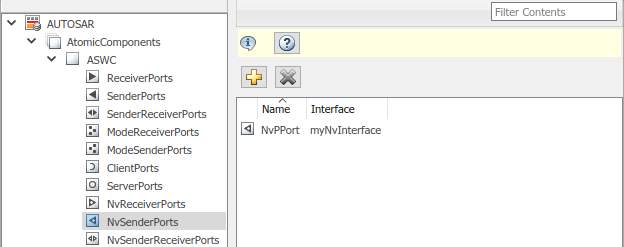
In the leftmost pane of the AUTOSAR Dictionary, select NvSenderPorts.
The NV sender ports view in the AUTOSAR Dictionary lists NV sender ports and their properties. You can:
Select an AUTOSAR NV sender port, and view and optionally reselect its associated NV data interface.
Rename an NV sender port by editing its name text.
To add an NV sender port, click the Add button
and use the Add Ports dialog box.
Specify a port name and associate it with an existing NV
interface.To remove an NV sender port, select the port and then click the Delete button
.
In the leftmost pane of the AUTOSAR Dictionary, select NvSenderReceiverPorts.
The NV sender-receiver ports view in the AUTOSAR Dictionary lists NV sender-receiver ports and their properties. You can:
Select an AUTOSAR NV sender-receiver port, and view and optionally reselect its associated NV data interface.
Rename an NV sender-receiver port by editing its name text.
To add an NV sender-receiver port, click the Add button
and use the Add Ports dialog box.
Specify a port name and associate it with an existing NV
interface.To remove an NV sender-receiver port, select the port and then click the Delete button
.
Note
AUTOSAR NV sender-receiver ports require AUTOSAR schema version 4.1 or higher. To select a schema version for the model, go to AUTOSAR Code Generation Options (Embedded Coder) in the Configuration Parameters dialog box.

Parameter Receiver Ports
The AUTOSAR Dictionary view of parameter receiver ports supports modeling the receiver side of AUTOSAR parameter communication in Simulink. You use the AUTOSAR Dictionary to configure AUTOSAR parameter receiver ports, parameter interfaces, and parameter data elements in your model. For more information, see Configure AUTOSAR Port Parameters for Communication with Parameter Software Component.
To configure AUTOSAR parameter receiver port elements and properties, open a model for which a mapped AUTOSAR software component has been created and open the AUTOSAR Dictionary. In the leftmost pane of the AUTOSAR Dictionary, expand the component name and select ParameterReceiverPorts.
The parameter receiver ports view in the AUTOSAR Dictionary lists parameter receiver ports and their properties. You can:
Select an AUTOSAR parameter receiver port, and view and optionally reselect its associated parameter interface.
Rename a parameter receiver port by editing its name text.
To add a parameter receiver port, click the Add button
and use the Add Ports dialog box. Specify
a port name and associate it with an existing parameter interface.To remove a parameter receiver port, select the port and then click the Delete button
.

Trigger Receiver Ports
The AUTOSAR Dictionary view of trigger receiver ports supports modeling the receiver side of AUTOSAR trigger communication in Simulink. You use the AUTOSAR Dictionary to configure AUTOSAR trigger receiver ports, trigger interfaces, and triggers in your model. For more information, see Configure Receiver for AUTOSAR External Trigger Event Communication.
To configure AUTOSAR trigger receiver port elements and properties, open a model for which a mapped AUTOSAR software component has been created and open the AUTOSAR Dictionary. In the leftmost pane of the AUTOSAR Dictionary, expand the component name and select TriggerReceiverPorts.
The trigger receiver ports view in the AUTOSAR Dictionary lists trigger receiver ports and their properties. You can:
Select an AUTOSAR trigger receiver port, and view and optionally reselect its associated trigger interface.
Rename a trigger receiver port by editing its name text.
To add a trigger receiver port, click the Add button
and use the Add Ports dialog box. Specify
a port name and associate it with an existing trigger interface.To remove a trigger receiver port, select the port and then click the Delete button
.

Configure AUTOSAR Runnables
The Runnables view in the AUTOSAR Dictionary supports modeling AUTOSAR runnable entities (runnables) and events, which implement aspects of internal AUTOSAR component behavior, in Simulink. You use the AUTOSAR Dictionary to configure AUTOSAR runnables and associated events that activate them. For more information, see Configure AUTOSAR Runnables and Events.
In the AUTOSAR Dictionary, runnables appear in a tree format under the component that owns them. To access runnable and event elements and their properties, you expand the component name.
To configure AUTOSAR runnable and event elements and properties, open a model for which a mapped AUTOSAR software component has been created and open the AUTOSAR Dictionary. In the leftmost pane of the AUTOSAR Dictionary, expand the component name and select Runnables.
The runnables view in the AUTOSAR Dictionary lists runnables for the AUTOSAR component. You can:
Rename an AUTOSAR runnable by editing its name text.
Modify the symbol name for a runnable. The specified AUTOSAR runnable symbol-name is exported in ARXML and C code. For example, if you change the symbol-name of
Runnable1fromRunnable1totest_symbol, the symbol-nametest_symbolappears in the exported ARXML and C code. Here is a sample of the exported ARXML descriptions:<RUNNABLE-ENTITY UUID="..."> <SHORT-NAME>Runnable1</SHORT-NAME> ... <SYMBOL>test_symbol</SYMBOL> ... </RUNNABLE-ENTITY>Here is a sample of the generated C code:
/* Model step function for TID1 */
void test_symbol(void)                 /* Explicit Task: Runnable1 */
{
...
}
Note
For an AUTOSAR server runnable — that is, a runnable with an
OperationInvokedEvent— the symbol name must match the Simulink server function name.For an AUTOSAR server runnable, set the runnable property
canBeInvokedConcurrentlyto designate whether to enforce concurrency constraints. For non-server runnables, leavecanBeInvokedConcurrentlyset tofalse. For more information, see Concurrency Constraints for AUTOSAR Server Runnables.To add a runnable, click the Add button
.To remove a runnable, select the runnable and then click the Delete button
.

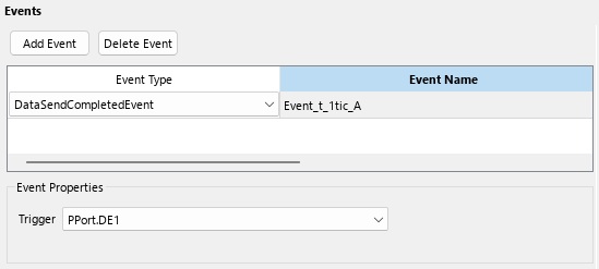
Select a runnable to see its list of associated events. The Events pane lists each AUTOSAR event with its type — TimingEvent, DataReceivedEvent, ModeSwitchEvent, OperationInvokedEvent, InitEvent, DataReceiveErrorEvent, or ExternalTriggerOccurredEvent — and name. You can rename an AUTOSAR event by editing its name text. You can use the buttons Add Event and Delete Event to add or delete events from a runnable.

If you select an event of type DataReceivedEvent, the runnable is activated by a DataReceivedEvent. Select the event name to display its Trigger property. Select a trigger for the event from the list of available trigger ports.

If you select an event of type DataReceiveErrorEvent, the runnable
is activated by a DataReceiveErrorEvent. Select the event
name to display its Trigger property. Select a trigger for the
event from the list of available trigger ports. For more information on using a
DataReceiveErrorEvent, see Configure AUTOSAR Receiver Port for DataReceiveErrorEvent.

If you select an event of type DataSendCompletedEvent, the
runnable is activated by a DataSendCompletedEvent. Select the
event name to display its Trigger property. Select a trigger for
the event from the list of available trigger ports. For more information on using a
DataSendCompletedEvent, see Configure AUTOSAR Sender Port for DataSendCompletedEvent.
If you select an event of type ModeSwitchEvent, the Mode
Activation and Mode Receiver Port properties are
displayed. Select a mode receiver port for the event from the list of configured
mode-receiver ports. Select a mode activation value for the event from the list of
values (OnEntry, OnExit, or
OnTransition). Based on the value you select, one or two
Mode Declaration drop-down lists appear. Select a mode (or two
modes) for the event, among those declared by the mode declaration group associated with
the Simulink inport that models the AUTOSAR mode-receiver port. For more information on
using a ModeSwitchEvent, see Configure AUTOSAR Mode-Switch Communication.

If you select an event of type OperationInvokedEvent, the runnable
becomes an AUTOSAR server runnable. Select the event name to display its
Trigger property. Select a trigger for the event from the list
of available server port and operation combinations. The Operation
Signature is displayed below the Trigger property.
For more information on using an OperationInvokedEvent, see
AUTOSAR Client-Server Communication.

If you select an event of type InitEvent, you can rename the event
by editing its name text. For more information on using an
InitEvent, see Configure AUTOSAR Initialization Runnable (R4.1).
Note
AUTOSAR InitEvents require AUTOSAR schema version 4.1 or higher. To select a schema version for the model, go to AUTOSAR Code Generation Options (Embedded Coder) in the Configuration Parameters dialog box.

If you select an event of type ExternalTriggerOccurredEvent, the
runnable is activated when an AUTOSAR software component or service signals an external
trigger event. Select the event name to display its Trigger
property. Select a trigger for the event from the list of available trigger receiver
port and trigger combinations. For more information on using an
ExternalTriggerOccurredEvent, see Configure Receiver for AUTOSAR External Trigger Event Communication.

Configure AUTOSAR Inter-Runnable Variables
The IRV view in the AUTOSAR Dictionary supports modeling AUTOSAR inter-runnable variables (IRVs), which connect runnables and implement aspects of internal AUTOSAR component behavior, in Simulink. You use the AUTOSAR Dictionary to create AUTOSAR IRVs and configure IRV data properties. For more information, see Configure AUTOSAR Data for Calibration and Measurement.
In the AUTOSAR Dictionary, IRVs appear in a tree format under the component that owns them. To access IRV elements and their properties, you expand the component name.
To configure AUTOSAR IRV elements and properties, open a model for which a mapped AUTOSAR software component has been created and open the AUTOSAR Dictionary. In the leftmost pane of the AUTOSAR Dictionary, expand the component name and select IRV.
The IRV view in the AUTOSAR Dictionary lists IRVs for the AUTOSAR component. You can:
Rename an AUTOSAR IRV by editing its name text.
Specify the level of calibration and measurement tool access to IRV data. Select an IRV and set its SwCalibrationAccess value to
ReadOnly,ReadWrite, orNotAccessible.Optionally specify the format to be used by calibration and measurement tools to display the IRV data. In the DisplayFormat field, enter an ANSI® C
printfformat specifier string. For example,%2.1dspecifies a signed decimal number, with a minimum width of two characters and a maximum precision of one digit, producing a displayed value such as12.2. For more information about constructing a format specifier string, see Configure DisplayFormat.Optionally specify a software address method for the IRV data. Select or enter a value for SwAddrMethod. AUTOSAR software components use
SwAddrMethods to group data in memory for access by calibration and measurement tools. For more information, see Configure AUTOSAR SwAddrMethods.To add an IRV, click the Add button
.To remove an IRV, select the IRV and then click the Delete button
.

Configure AUTOSAR Parameters
The Parameters view in the AUTOSAR Dictionary supports modeling AUTOSAR internal calibration parameters, for use with AUTOSAR integrated and distributed lookups, in Simulink. You use the AUTOSAR Dictionary to create AUTOSAR internal parameters and configure parameter data properties. For port-based calibration parameters, you create Parameter Interfaces.
In the AUTOSAR Dictionary, internal parameters appear in a tree format under the component that owns them. To access parameter elements and their properties, you expand the component name.
To configure AUTOSAR parameter elements and properties, open a model for which a mapped AUTOSAR software component has been created and open the AUTOSAR Dictionary. In the leftmost pane of the AUTOSAR Dictionary, expand the component name and select Parameters.
The parameters view in the AUTOSAR Dictionary lists internal parameters for the AUTOSAR component. You can:
Rename an AUTOSAR parameter by editing its name text.
Specify the level of calibration and measurement tool access to parameters. Select a parameter and set its SwCalibrationAccess value to
ReadOnly,ReadWrite, orNotAccessible.Optionally specify the format to be used by calibration and measurement tools to display the parameter data. In the DisplayFormat field, enter an ANSI C
printfformat specifier string. For example,%2.1dspecifies a signed decimal number, with a minimum width of two characters and a maximum precision of one digit, producing a displayed value such as12.2. For more information about constructing a format specifier string, see Configure DisplayFormat.Optionally specify a software address method for the parameter data. Select or enter a value for SwAddrMethod. AUTOSAR software components use
SwAddrMethods to group data in memory for access by calibration and measurement tools. For more information, see Configure AUTOSAR SwAddrMethods.To add an internal parameter, click the Add button
.To remove an internal parameter, select the parameter and then click the Delete button
.

Configure AUTOSAR Communication Interfaces
An AUTOSAR software component uses communication interfaces defined in the AUTOSAR standard, including sender-receiver (S-R), client-server (C-S), mode-switch (M-S), nonvolatile (NV) data, trigger, and parameter interfaces. In the AUTOSAR Dictionary, communication interfaces appear in a tree format under the interface type name. To access interface elements and their properties, you expand the interface type name.
Sender-Receiver Interfaces
The S-R Interfaces view in the AUTOSAR Dictionary supports modeling AUTOSAR sender-receiver (S-R) communication in Simulink. You use the AUTOSAR Dictionary to configure AUTOSAR S-R ports, S-R interfaces, and S-R data elements in your model. For more information, see Configure AUTOSAR Sender-Receiver Communication and Configure AUTOSAR Queued Sender-Receiver Communication.
To configure AUTOSAR S-R interface elements and properties, open a model for which a mapped AUTOSAR software component has been created and open the AUTOSAR Dictionary.
In the leftmost pane of the AUTOSAR Dictionary, select S-R Interfaces.
The S-R interfaces view in the AUTOSAR Dictionary lists AUTOSAR sender-receiver interfaces and their properties. You can:
Select an S-R interface and then select a menu value to specify whether or not it is a service.
Rename an S-R interface by editing its name text.
To add an S-R interface, click the Add button
and use the Add Interfaces dialog box. Specify an interface name, the number of data elements it contains, whether the interface is a service, and the path of the Interface package.To remove an S-R interface, select the interface and then click the Delete button
.

In the leftmost pane of the AUTOSAR Dictionary, expand S-R Interfaces and select an S-R interface from the list.
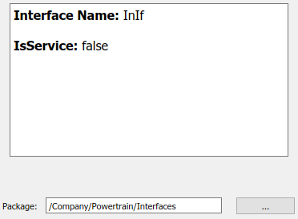
The S-R interface view in the AUTOSAR Dictionary displays the name of the selected S-R interface, whether or not it is a service, and the AUTOSAR package to be generated for the interface.
To modify the AUTOSAR package for the interface, you can do either of the following:
Enter a package path in the Package parameter field.
Click the button to the right of the Package field to open the AUTOSAR Package Browser. Use the browser to navigate to an existing package or create a new package. When you select a package in the browser and click Apply, the interface Package parameter value is updated with your selection. For more information about the AUTOSAR Package Browser, see Configure AUTOSAR Package for Component, Interface, CompuMethod, or SwAddrMethod.
In the leftmost pane of the AUTOSAR Dictionary, expand the selected interface and select DataElements.
The data elements view in the AUTOSAR Dictionary lists AUTOSAR sender-receiver interface data elements and their properties. You can:
Select an S-R interface data element and edit its name value.
Specify the level of calibration and measurement tool access to S-R interface data elements. Select a data element and set its SwCalibrationAccess value to
ReadOnly,ReadWrite, orNotAccessible.Optionally specify the format to be used by calibration and measurement tools to display the data element. In the DisplayFormat field, enter an ANSI C
printfformat specifier string. For example,%2.1dspecifies a signed decimal number, with a minimum width of two characters and a maximum precision of one digit, producing a displayed value such as12.2. For more information about constructing a format specifier string, see Configure DisplayFormat.Optionally specify a description for the data element in the LongName field.
Optionally specify a software address method for the data element. Select or enter a value for SwAddrMethod. AUTOSAR software components use
SwAddrMethods to group data in memory for access by calibration and measurement tools. For more information, see Configure AUTOSAR SwAddrMethods.To add a data element, click the Add button
.To remove a data element, select the data element and then click the Delete button
.

Mode-Switch Interfaces
The M-S Interfaces view in the AUTOSAR Dictionary supports modeling AUTOSAR mode-switch (M-S) communication in Simulink. You use the AUTOSAR Dictionary to configure AUTOSAR M-S ports and M-S interfaces in your model. For more information, see Configure AUTOSAR Mode-Switch Communication.
To configure AUTOSAR M-S interface elements and properties, open a model for which a mapped AUTOSAR software component has been created and open the AUTOSAR Dictionary.
In the leftmost pane of the AUTOSAR Dictionary, select M-S Interfaces.
The M-S interfaces view in the AUTOSAR Dictionary lists AUTOSAR mode-switch interfaces and their properties. You can:
Select an M-S interface, specify whether or not it is a service, and modify the name of its associated mode group.
The IsService property defaults to
true. Thetruesetting assumes that the M-S interface participates in run-time mode management, for example, performed by the Basic Software Mode Manager.A mode group contains mode values, declared in Simulink using enumeration. For more information, see Configure AUTOSAR Mode-Switch Communication.
Rename an M-S interface by editing its name text.
To add an M-S interface, click the Add button
and use the Add Interfaces dialog box. Specify an interface name, the name of a mode group, whether the interface is a service, and the path of the Interface package.To remove an M-S interface, select the interface and then click the Delete button
.

In the leftmost pane of the AUTOSAR Dictionary, expand M-S Interfaces and select an M-S interface from the list.
The M-S interface view in the AUTOSAR Dictionary displays the name of the selected M-S interface, whether or not it is a service, its associated mode group, and the AUTOSAR package for the interface.
To modify the AUTOSAR package for the interface, you can do either of the following:
Enter a package path in the Package parameter field.
Click the button to the right of the Package field to open the AUTOSAR Package Browser. Use the browser to navigate to an existing package or create a new package. When you select a package in the browser and click Apply, the interface Package parameter value is updated with your selection. For more information about the AUTOSAR Package Browser, see Configure AUTOSAR Package for Component, Interface, CompuMethod, or SwAddrMethod.

Client-Server Interfaces
The C-S Interfaces view in the AUTOSAR Dictionary supports modeling AUTOSAR client-server (C-S) communication in Simulink. You use the AUTOSAR Dictionary to configure AUTOSAR C-S ports, C-S interfaces, and C-S operations in your model. For more information, see AUTOSAR Client-Server Communication.
To configure AUTOSAR C-S interface elements and properties, open a model for which a mapped AUTOSAR software component has been created and open the AUTOSAR Dictionary.
In the leftmost pane of the AUTOSAR Dictionary, select C-S Interfaces.
The C-S interfaces view in the AUTOSAR Dictionary lists AUTOSAR client-server interfaces and their properties. You can:
Select a C-S interface and then select a menu value to specify whether or not it is a service.
Rename a C-S interface by editing its name text.
To add a C-S interface, click the Add button
and use the Add Interfaces dialog
box. Specify an interface name, the number of associated operations
it contains, whether the interface is a service, and the path of the
Interface package.To remove a C-S interface, select the interface and then click the Delete button
.

In the leftmost pane of the AUTOSAR Dictionary, expand C-S Interfaces and select a C-S interface from the list.
The C-S interface view in the AUTOSAR Dictionary displays the name of the selected C-S interface, whether or not it is a service, and the AUTOSAR package for the interface.
To modify the AUTOSAR package for the interface, you can do either of the following:
Enter a package path in the Package parameter field.
Click the button to the right of the Package field to open the AUTOSAR Package Browser. Use the browser to navigate to an existing package or create a new package. When you select a package in the browser and click Apply, the interface Package parameter value is updated with your selection. For more information about the AUTOSAR Package Browser, see Configure AUTOSAR Package for Component, Interface, CompuMethod, or SwAddrMethod.

In the leftmost pane of the AUTOSAR Dictionary, expand the selected interface and select Operations.
The operations view in the AUTOSAR Dictionary lists AUTOSAR client-server interface operations. You can:
Select a C-S interface operation and edit its name value.
To add an operation, click the Add button
and use the Add Operation dialog
box. In the dialog box, specify an operation name and an associated
Simulink function. To create operation arguments from a
Simulink function, select the associated Simulink function among those present in the configuration. If
you are creating an operation without arguments, select
None.To remove an operation, select the operation and then click the Delete button
.

In the leftmost pane of the AUTOSAR Dictionary, expand Operations and select an operation from the list.
The operations view in the AUTOSAR Dictionary displays the name of the selected C-S operation.

In the leftmost pane of the AUTOSAR Dictionary, expand the selected operation and select Arguments.
The arguments view in the AUTOSAR Dictionary lists AUTOSAR client-server operation arguments and their properties. You can:
Select a C-S operation argument and edit its name value.
Specify the direction of the C-S operation argument. Set its Direction value to
In,Out,InOut, orError. SelectErrorif the operation argument returns application error status. For more information, see Configure AUTOSAR Client-Server Error Handling.Specify the level of calibration and measurement tool access to C-S operation arguments. Select an argument and set its SwCalibrationAccess value to
ReadOnly,ReadWrite, orNotAccessible.Optionally specify the format to be used by calibration and measurement tools to display the argument. In the DisplayFormat field, enter an ANSI C
printfformat specifier string. For example,%2.1dspecifies a signed decimal number, with a minimum width of two characters and a maximum precision of one digit, producing a displayed value such as12.2. For more information about constructing a format specifier string, see Configure DisplayFormat.Optionally specify a software address method for the argument. Select or enter a value for SwAddrMethod. AUTOSAR software components use
SwAddrMethods to group data in memory for access by calibration and measurement tools. For more information, see Configure AUTOSAR SwAddrMethods.To add an argument, click the Add button
.To remove an argument, select the argument and then click the Delete button
.

The displayed server operation arguments were created from the following Simulink Function block.

Nonvolatile Data Interfaces
The NV Interfaces view in the AUTOSAR Dictionary supports modeling AUTOSAR nonvolatile (NV) data communication in Simulink. You use the AUTOSAR Dictionary to configure AUTOSAR NV ports, NV interfaces, and NV data elements in your model. For more information, see Configure AUTOSAR Nonvolatile Data Communication.
To configure AUTOSAR NV interface elements and properties, open a model for which a mapped AUTOSAR software component has been created and open the AUTOSAR Dictionary.
In the leftmost pane of the AUTOSAR Dictionary, select NV Interfaces.
The NV interfaces view in the AUTOSAR Dictionary lists AUTOSAR NV data interfaces and their properties. You can:
Select an NV interface and then select a menu value to specify whether or not it is a service.
Rename an NV interface by editing its name text.
To add an NV interface, click the Add button
and use the Add
Interfaces dialog box. Specify an interface name, the
number of associated data elements it contains, whether the
interface is a service, and the path of the Interface
package.To remove an NV interface, select the interface and then click the Delete button
.

In the leftmost pane of the AUTOSAR Dictionary, expand NV Interfaces and select an NV interface from the list.
The NV interface view in the AUTOSAR Dictionary displays the name of the selected NV data interface, whether or not it is a service, and the AUTOSAR package to be generated for the interface.
To modify the AUTOSAR package for the interface, you can do either of the following:
Enter a package path in the Package parameter field.
Click the button to the right of the Package field to open the AUTOSAR Package Browser. Use the browser to navigate to an existing package or create a new package. When you select a package in the browser and click Apply, the interface Package parameter value is updated with your selection. For more information about the AUTOSAR Package Browser, see Configure AUTOSAR Package for Component, Interface, CompuMethod, or SwAddrMethod.

In the leftmost pane of the AUTOSAR Dictionary, expand the selected interface and select DataElements.
The data elements view in the AUTOSAR Dictionary lists AUTOSAR NV interface data elements and their properties. You can:
Select an NV interface data element and edit its name value.
Specify the level of calibration and measurement tool access to the NV interface data elements. Select a data element and set its SwCalibrationAccess value to
ReadOnly,ReadWrite, orNotAccessible.Optionally specify the format to be used by calibration and measurement tools to display the data element. In the DisplayFormat field, enter an ANSI C
printfformat specifier string. For example,%2.1dspecifies a signed decimal number, with a minimum width of two characters and a maximum precision of one digit, producing a displayed value such as12.2. For more information about constructing a format specifier string, see Configure DisplayFormat.Optionally specify a software address method for the data element. Select or enter a value for SwAddrMethod. AUTOSAR software components use
SwAddrMethods to group data in memory for access by calibration and measurement tools. For more information, see Configure AUTOSAR SwAddrMethods.To add a data element, click the Add button
.To remove a data element, select the data element and then click the Delete button
.

Parameter Interfaces
The Parameter Interfaces view in the AUTOSAR Dictionary supports modeling the receiver side of AUTOSAR parameter communication in Simulink. You use the AUTOSAR Dictionary to configure AUTOSAR parameter receiver ports, parameter interfaces, and parameter data elements in your model. For more information, see Configure AUTOSAR Port Parameters for Communication with Parameter Software Component.
To configure AUTOSAR parameter interface elements and properties, open a model for which a mapped AUTOSAR software component has been created and open the AUTOSAR Dictionary.
In the leftmost pane of the AUTOSAR Dictionary, select Parameter Interfaces.
The parameter interfaces view in the AUTOSAR Dictionary lists AUTOSAR parameter interfaces and their properties. You can:
Select a parameter interface and then select a menu value to specify whether or not it is a service.
Rename a parameter interface by editing its name text.
To add a parameter interface, click the Add button
and use the Add Interfaces dialog box. Specify an interface name, the number of associated data elements it contains, whether the interface is a service, and the path of the Interface package.To remove a parameter interface, select the interface and then click the Delete button
.

In the leftmost pane of the AUTOSAR Dictionary, expand Parameter Interfaces and select a parameter interface from the list.
The parameter interface view in the AUTOSAR Dictionary displays the name of the selected parameter interface, whether or not it is a service, and the AUTOSAR package to generate for the interface.
To modify the AUTOSAR package for the interface, you can do either of the following:
Enter a package path in the Package parameter field.
Click the button to the right of the Package field to open the AUTOSAR Package Browser. Use the browser to navigate to an existing package or create a new package. When you select a package in the browser and click Apply, the interface Package parameter value is updated with your selection. For more information about the AUTOSAR Package Browser, see Configure AUTOSAR Package for Component, Interface, CompuMethod, or SwAddrMethod.

In the leftmost pane of the AUTOSAR Dictionary, expand the selected interface and select DataElements.
The data elements view in the AUTOSAR Dictionary lists AUTOSAR parameter interface data elements and their properties. You can:
Select a parameter interface data element and edit its name value.
Specify the level of calibration and measurement tool access to parameter interface data elements. Select a data element and set its SwCalibrationAccess value to
ReadOnly,ReadWrite, orNotAccessible.Optionally specify the format to be used by calibration and measurement tools to display the data element. In the DisplayFormat field, enter an ANSI C
printfformat specifier string. For example,%2.1dspecifies a signed decimal number, with a minimum width of two characters and a maximum precision of one digit, producing a displayed value such as12.2. For more information about constructing a format specifier string, see Configure DisplayFormat.Optionally specify a software address method for the data element. Select or enter a value for SwAddrMethod. AUTOSAR software components use
SwAddrMethods to group data in memory for access by calibration and measurement tools. For more information, see Configure AUTOSAR SwAddrMethods.To add a data element, click the Add button
.To remove a data element, select the data element and then click the Delete button
.

Trigger Interfaces
The Trigger Interfaces view in the AUTOSAR Dictionary supports modeling the receiver side of AUTOSAR trigger communication in Simulink. You use the AUTOSAR Dictionary to configure AUTOSAR trigger receiver ports, trigger interfaces, and triggers in your model. For more information, see Configure Receiver for AUTOSAR External Trigger Event Communication.
To configure AUTOSAR trigger interface elements and properties, open a model for which a mapped AUTOSAR software component has been created and open the AUTOSAR Dictionary.
In the leftmost pane of the AUTOSAR Dictionary, select Trigger Interfaces.
The trigger interfaces view in the AUTOSAR Dictionary lists AUTOSAR trigger interfaces and their properties. You can:
Select a trigger interface and then select a menu value to specify whether or not it is a service.
Rename a trigger interface by editing its name text.
To add a trigger interface, click the Add button
and use the Add Interfaces dialog box. Specify an interface name, the number of associated triggers it contains, whether the interface is a service, and the path of the Interface package.To remove a trigger interface, select the interface and then click the Delete button
.

In the leftmost pane of the AUTOSAR Dictionary, expand Trigger Interfaces and select a trigger interface from the list.
The trigger interface view in the AUTOSAR Dictionary displays the name of the selected trigger interface, whether or not it is a service, and the AUTOSAR package to be generated for the interface.
To modify the AUTOSAR package for the interface, you can do either of the following:
Enter a package path in the Package parameter field.
Click the button to the right of the Package field to open the AUTOSAR Package Browser. Use the browser to navigate to an existing package or create a new package. When you select a package in the browser and click Apply, the interface Package parameter value is updated with your selection. For more information about the AUTOSAR Package Browser, see Configure AUTOSAR Package for Component, Interface, CompuMethod, or SwAddrMethod.

In the leftmost pane of the AUTOSAR Dictionary, expand the selected interface and select Triggers.
The triggers view in the AUTOSAR Dictionary lists AUTOSAR triggers and their properties. You can:
Select a trigger and edit its name value.
If the trigger is periodic, you can use CseCode and CseCodeFactor to specify a period for the trigger. (Otherwise, leave the period unspecified.)
To specify the time base of the period, select a value from the CseCode menu. The values are based on ASAM codes for scaling unit (CSE).
To specify the scaling factor for the period, enter an integer value in the CseCodeFactor field.
For example, to specify a period of 15 milliseconds, set CseCode to
CSE3(1 millisecond) and set CseCodeFactor to15.CseCode Time Base NoneUnspecified (trigger is not periodic)
CSE01 µsec (microsecond)
CSE110 µsec
CSE2100 µsec
CSE31 msec (millisecond)
CSE410 msec
CSE5100 msec
CSE61 second
CSE710 seconds
CSE81 minute
CSE91 hour
CSE101 day
CSE201 fs (femtosecond)
CSE2110 fs
CSE22100 fs
CSE231 ps (picosecond)
CSE2410 ps
CSE25100 ps
CSE261 ns (nanosecond)
CSE2710 ns
CSE28100 ns
CSE100Angular degrees
CSE101Revolutions (1 = 360 degrees)
CSE102Cycle (1 = 720 degrees)
CSE997Computing cycle
CSE998When frame available
CSE999Always when there is a new value
CSE1000Nondeterministic (no fixed scaling)
To add a trigger, click the Add button
.To remove a trigger, select the trigger and then click the Delete button
.

Configure AUTOSAR Computation Methods
The CompuMethods view in the AUTOSAR Dictionary supports modeling AUTOSAR computation methods (CompuMethods), which specify conversions between internal values and physical representations of AUTOSAR data, in Simulink. You use the AUTOSAR Dictionary to create and configure AUTOSAR CompuMethods. For more information, see Create, Import, and Configure AUTOSAR Computation Methods.
To configure AUTOSAR CompuMethod elements and properties, open a model for which a mapped AUTOSAR software component has been created and open the AUTOSAR Dictionary. Select CompuMethods.
The CompuMethods view in the AUTOSAR Dictionary displays CompuMethods and their properties. You can:
Select a CompuMethod and modify properties, such as name, category, unit, display format for calibration and measurement, AUTOSAR package to be generated for the CompuMethod, and a list of Simulink data types that reference the CompuMethod. For property descriptions, see Configure AUTOSAR Computation Methods Properties.
To add a CompuMethod, click the Add button
and use the Add CompuMethod dialog box, which is described below.To remove a CompuMethod, select the CompuMethod and then click the Delete button
.
To modify the AUTOSAR package for a CompuMethod, you can do either of the following:
Enter a package path in the Package parameter field.
Click the button to the right of the Package field to open the AUTOSAR Package Browser. Use the browser to navigate to an existing package or create a new package. When you select a package in the browser and click Apply, the CompuMethod Package parameter value is updated with your selection. For more information about the AUTOSAR Package Browser, see Configure AUTOSAR Package for Component, Interface, CompuMethod, or SwAddrMethod.
To associate a CompuMethod with a Simulink data type used in the model, select a CompuMethod and click the Add button to the right of Simulink DataTypes. This action opens a dialog box with a list of available data types. To add a data type to the Simulink DataTypes list, select the data type and click OK. To remove a data type from the Simulink DataTypes list, select the data type and click Remove.

The Add CompuMethod dialog box lets you create a CompuMethod and specify its initial properties, such as name, category, unit, display format for calibration and measurement, AUTOSAR package to be generated for the CompuMethod, and a Simulink data type that references the CompuMethod.

Clicking the Add button to the right of Simulink DataTypes opens the Set Simulink data type to AUTOSAR CompuMethod dialog box. This dialog box lets you select a Simulink data type to add to Simulink DataTypes, the list of Simulink data types that reference a CompuMethod. In the list of available data types, select a Simulink.NumericType or Simulink.AliasType, or enter the name of a Simulink enumerated type.

Configure AUTOSAR SwAddrMethods
The SwAddrMethods view in the Architectural Data Editor supports modeling AUTOSAR software address methods (SwAddrMethods). AUTOSAR software components use SwAddrMethods to group data and function definitions in memory, primarily for efficiency, performance, and data access by run-time calibration tools. In the Architectural Data Editor, you can view or create AUTOSAR SwAddrMethods and then assign SwAddrMethods to data and functions that you want to group together. For more information, see Configure SwAddrMethod.
To configure AUTOSAR SwAddrMethod elements and properties, open a model for which a mapped AUTOSAR software component has been created and open the Architectural Data Editor from the Interfaces tab at the bottom left of the model window. Select the SwAddrMethods tab.
The SwAddrMethods view in the Architectural Data Editor displays SwAddrMethods and their properties. You can:
Select a SwAddrMethod and modify properties, such as name, section type, and AUTOSAR package to be generated for the SwAddrMethod.
To modify the section type, select a value from the SectionType drop-down list. The listed values correspond to SwAddrMethod section types listed in the AUTOSAR standard.
SectionType Value SwAddrMethod Section Type CalibrationVariablesCALIBRATION-VARIABLES CalprmCALPRM CodeCODE ConfigDataCONFIG-DATA ConstCONST ExcludeFromFlashEXCLUDE-FROM-FLASH VarVAR To add a SwAddrMethod, click the Add button
and use the Add SwAddrMethod dialog box. Specify a SwAddrMethod name, a section type, and the path of the SwAddrMethod package.To remove a SwAddrMethod, select the SwAddrMethod and then click the Delete button
.
To modify the AUTOSAR package for a SwAddrMethod, you can do either of the following:
Enter a package path in the Package parameter field.
Click the button to the right of the Package field to open the AUTOSAR Package Browser. Use the browser to navigate to an existing package or create a new package. When you select a package in the browser and click Apply, the SwAddrMethod Package parameter value is updated with your selection. For more information about the AUTOSAR Package Browser, see Configure AUTOSAR Package for Component, Interface, CompuMethod, or SwAddrMethod.

Configure AUTOSAR XML Options
To configure AUTOSAR XML options for ARXML file export, open a model for which a mapped AUTOSAR software component has been created and open the AUTOSAR Dictionary. Select XML Options.
The XML options view in the AUTOSAR Dictionary displays XML export parameters and their values. You can configure:
XML options source (for components in architecture modeling)
XML file packaging for AUTOSAR elements created in Simulink
AUTOSAR package paths
AUTOSAR platform types naming behavior and packaging
Aspects of exported AUTOSAR XML content

Configure AUTOSAR XML Export
This example configures AUTOSAR XML export parameter Exported XML file packaging (ArxmlFilePackaging) and AUTOSAR package paths.
Configure XML Export Options
For more information regarding XML Options see, AUTOSAR XML Options Settings.
hModel = "autosar_swc_counter";
open_system(hModel);
arProps = autosar.api.getAUTOSARProperties(hModel);
Set exported AUTOSAR XML file packaging to Single file
get(arProps,"XmlOptions","ArxmlFilePackaging")
ans =
'Modular'
set(arProps,"XmlOptions","ArxmlFilePackaging","SingleFile");
get(arProps,"XmlOptions","ArxmlFilePackaging")
ans =
'SingleFile'
Configure AUTOSAR Package Paths
For other AUTOSAR package path property names, see Configure AUTOSAR Packages and Paths.
hModel = "autosar_swc_counter";
open_system(hModel);
arProps = autosar.api.getAUTOSARProperties(hModel);
Specify AUTOSAR application data type package path for XML export.
get(arProps,"XmlOptions","ApplicationDataTypePackage")
ans =
'/Company/Powertrain/DataTypes/ApplDataTypes'
set(arProps,"XmlOptions","ApplicationDataTypePackage","/Company/Powertrain/DataTypes/ADTs");
get(arProps,"XmlOptions","ApplicationDataTypePackage")
ans =
'/Company/Powertrain/DataTypes/ADTs'
XML Options Source
The XML options view displays the parameter XML Options Source. If the current component model is contained in an AUTOSAR architecture model, this parameter indicates which XML options to use in model builds. Specify Inherit from AUTOSAR architecture model to use shared architecture model XML option settings, which promote consistency across the model hierarchy. Specify Inlined to override the shared settings with the component model local XML option settings.
If the current component model is not contained in an AUTOSAR architecture model, the XML Options Source parameter has no effect.
Alternatively, you can programmatically configure the XML options source by calling the AUTOSAR set function. For property XmlOptionsSource, specify either Inlined or Inherit. For example:
arProps = autosar.api.getAUTOSARProperties(hModel);
set(arProps,"XmlOptions",XmlOptionsSource="Inlined");
For more information about architecture model XML options, see Export Composition and Component ARXML Descriptions from AUTOSAR Blockset Architectures.
Exported XML File Packaging
In the XML options view, you can specify the granularity of XML file packaging for AUTOSAR elements created in Simulink. (Imported AUTOSAR XML files retain their file structure, as described in Round-Trip Preservation of AUTOSAR XML File Structure and Element Information.) Select one of the following values for Exported XML file packaging.
Single file— Exports XML into a single file,modelname.arxmlModular— Exports XML into multiple files, named according to the type of information contained.Exported File Name By Default Contains... modelName_component.arxmlmodelName_component.arxmlcontains descriptions of software components, including:Ports
Events
Runnables
Inter-runnable variables (IRVs)
Included data type sets
Component-scoped parameters and variables
In addition to software components, the component file contains descriptions of packageable elements that the exporter does not move to data type, implementation, interface, or timing files based on the AUTOSAR element category.
modelName_datatype.arxmlmodelName_datatype.arxmlcontains descriptions of Data types and related elements, including:Application and implementation data types
Software base types
Data type mapping sets
Constant specifications
Physical data constraints
System constants
Software address methods
Mode declaration groups
Computation methods
Units and unit groups
Software record layouts
Internal data constraints
modelName_implementation.arxmlmodelName_implementation.arxmlcontains descriptions of software component implementation, including code descriptors.
modelName_interface.arxmlmodelName_interface.arxmlcontains descriptions of interfaces that include Sender-Receiver, Client-Server, Mode-Switch, Nonvolatile data, parameter, and trigger interfaces. The interfaces include type-specific elements, such as S-R data elements, C-S operations, port-based parameters, or triggers.
modelName_timing.arxmlThis file is generated only for a multi-runnable model.
This file defines the execution order constraints in the model.
For more information, see Configure AUTOSAR Runnable Execution Order.
Alternatively, you can programmatically configure exported XML file packaging by calling the AUTOSAR set function. For property ArxmlFilePackaging, specify either SingleFile or Modular. For example:
arProps = autosar.api.getAUTOSARProperties(hModel);
set(arProps,"XmlOptions",ArxmlFilePackaging="SingleFile");
For more information, see Generate AUTOSAR C and XML Files.
AUTOSAR Package Paths
In the XML options view, you can configure AUTOSAR packages (AR-PACKAGEs), which contain groups of AUTOSAR elements and reside in a hierarchical AR-PACKAGE structure. (The AR-PACKAGE structure for a component is logically distinct from the ARXML file partitioning selected with the XML option Exported XML file packaging or imported from AUTOSAR XML files.) For more information about AUTOSAR packages, see Configure AUTOSAR Packages.
Inspect and modify the AUTOSAR package paths:
Grouped under the heading Package Paths.

Grouped under the heading Additional Packages.

Alternatively, you can programmatically configure an AUTOSAR package path by calling the AUTOSAR set function. Specify a package property name and a package path. For example:
arProps = autosar.api.getAUTOSARProperties(hModel);
set(arProps,"XmlOptions","ApplicationDataTypePackage", ...
        "/Company/Powertrain/DataTypes/ApplDataTypes");
Note
The DataTypePackage path must be different from the paths
of these packages:
ApplicationDataTypePackagePlatformDataTypePackageSwBaseTypePackage
For more information about AUTOSAR package property names and defaults, see Configure AUTOSAR Packages and Paths.
AUTOSAR Platform Types
In the XML options view, you can configure aspects of the AUTOSAR platform type packaging and naming behavior.
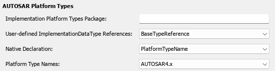
You can:
Specify the top-level package name for AUTOSAR implementation platform types and base types by entering the package name in the Implementation Platform Types Package field.
Implementation platform types are grouped as an
ImplementationDataTypessubpackage. Base types are grouped as aBaseTypessubpackage.For
ModularARXML export, the top-level package and its content is exported to thestub/file.modelname_platformtypes.arxmlSpecify the implementation data type reference behavior. Select either of the following values for User-defined Implementation Types References:
PlatformTypeReference— User-defined implementation data types reference an AUTOSAR implementation data type (CATEGORYis set toTYPE_REFERENCEin the ARXML).BaseTypeReference— User-defined implementation data types reference an SW base type (CATEGORYis set toVALUEin the ARXML).
Control whether the native declaration inherits the AUTOSAR platform type name or uses a C integral type name. Select either of the following values for Native Declaration:
PlatformTypeName— The native declaration inherits the AUTOSAR platform type name.CIntegralTypeName— The native declaration uses a C integral type name according to the hardware configuration specified in the model settings.
Alternatively, you can programmatically configure AUTOSAR platform type XML options by calling
the AUTOSAR set function. Specify a property name and value.
The valid property names are PlatformDataTypePackage,
UsePlatformTypeReferences, and
NativeDeclaration. For example:
arProps = autosar.api.getAUTOSARProperties(hModel);
set(arProps,"XmlOptions",PlatformDataTypePackage="/AUTOSAR_PlatformTypes");
set(arProps,"XmlOptions",UsePlatformTypeReferences="PlatformTypeReference");
set(arProps,"XmlOptions",NativeDeclaration="PlatformTypeName");
Additional XML Options
In the XML options view, under the heading Additional Options, you can configure aspects of exported AUTOSAR XML content.

You can:
Optionally override the default behavior for generating AUTOSAR application data types in ARXML code. To force generation of an application data type for each AUTOSAR data type, change the value of ImplementationDataType Reference from
AllowedtoNotAllowed. For more information, see Control Application Data Type Generation.Control the default value of the SwCalibrationAccess property of generated AUTOSAR measurement variables, calibration parameters, and signal and parameter data objects. Select one of the following values for SwCalibrationAccess DefaultValue:
ReadOnly— Read access only.ReadWrite(default) — Read and write access.NotAccessible— Not accessible with calibration and measurement tools.
For more information, see Configure SwCalibrationAccess.
Control the direction of CompuMethod conversion for linear-function CompuMethods. Select one of the following values for CompuMethod Direction:
InternalToPhys(default) — GenerateCompuMethodsections for conversion of internal values into their physical representations.PhysToInternal— GenerateCompuMethodsections for conversion of physical values into their internal representations.Bidirectional— GenerateCompuMethodsections for both internal-to-physical and physical-to-internal conversion directions.
For more information, see Configure CompuMethod Direction for Linear Functions.
Optionally override the default behavior for generating internal data constraint information for AUTOSAR implementation data types in ARXML code. To force export of internal data constraints for implementation data types, select the option Internal DataConstraints Export. For more information, see Configure AUTOSAR Internal Data Constraints for Export.
Optionally override the default behavior for exporting settings for lookup table constants. By default the settings for lookup table constants are exported. You can disable or enable this export by selecting the option Export Lookup Table Application Value Specification.
You can optionally override and set the binding time for variation points, excluding proxies and AUTOSAR data types. Select one of the following values for VariationPoint Binding Time:
PreCompileTime— Set the binding time for variation points to before compile time.CodeGenerationTime— Set the binding time for variation points to be at code generation.
To set the binding time for variation point proxies use the Variant activation time property on supported variant blocks.
Alternatively, you can programmatically configure the additional XML options by calling the
AUTOSAR set function. Specify a property name and value. The
valid property names are ImplementationTypeReference,
SwCalibrationAccessDefault,
CompuMethodDirection,
InternalDataConstraintExport,
ExportLookupTableApplicationValueSpecification, and
VpBindingTimeOverride. For example:
arProps = autosar.api.getAUTOSARProperties(hModel);
set(arProps,"XmlOptions",ImplementationTypeReference="NotAllowed");
set(arProps,"XmlOptions",SwCalibrationAccessDefault="ReadOnly");
set(arProps,"XmlOptions",CompuMethodDirection="PhysToInternal");
set(arProps,"XmlOptions",InternalDataConstraintExport=true);
set(arProps,"XmlOptions",ExportLookupTableApplicationValueSpecification=true);
set(arProps,"XmlOptions",VpBindingTimeOverride="PreCompileTime");