CI Controller
Compression-ignition controller that includes air mass flow, torque, and EGR estimation
Libraries:
Powertrain Blockset /
Propulsion /
Combustion Engine Controllers
Description
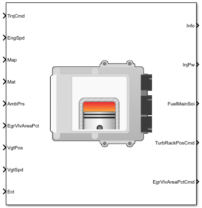
The CI Controller block implements a compression-ignition (CI) controller with air mass flow, torque, exhaust gas recirculation (EGR) flow, exhaust back-pressure, and exhaust gas temperature estimation. You can use the CI Controller block in engine control design or performance, fuel economy, and emission tradeoff studies. The core engine block requires the commands that are output from the CI Controller block.
The block uses the commanded torque and measured engine speed to determine these open-loop actuator commands:
Injector pulse-width
Fuel injection timing
Variable geometry turbocharger (VGT) rack position
EGR valve area percent
The CI Controller block has two subsystems:
The
Controllersubsystem — Determines the commands based on tables that are functions of commanded torque and measured engine speed.Based On Determines Commands for Commanded torque
Measured engine speed
Injector pulse-width
Fuel injection timing
VGT rack position
EGR valve area percent
The
Estimatorsubsystem — Determines estimates based on these engine attributes.Based On Estimates Measured engine speed
Fuel injection timing
Cycle average intake manifold pressure and temperature
Fuel injector pulse-width
Absolute ambient pressure
EGR valve area percent
VGT rack position
VGT speed
Air mass flow
Torque
Exhaust gas temperature
Exhaust gas back-pressure
EGR valve gas mass flow
The figure illustrates the signal flow.
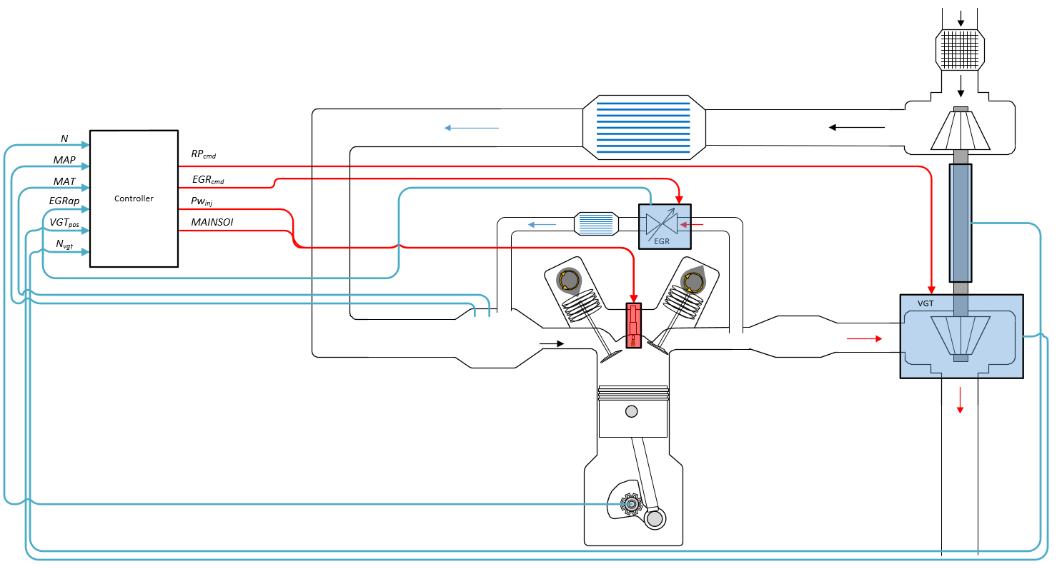
The figure uses these variables.
| N | Engine speed |
| MAP | Cycle average intake manifold absolute pressure |
| MAT | Cycle average intake manifold gas absolute temperature |
| EGRap, EGRcmd | EGR valve area percent and EGR valve area percent command, respectively |
| VGTpos |
VGT rack position |
| Nvgt |
Corrected turbocharger speed |
| RPcmd |
VGT rack position command |
|
Fuel injector pulse-width | |
| MAINSOI | Start of injection timing for main fuel injection pulse |
The Model-Based Calibration Toolbox™ was used to develop the tables that are available with the Powertrain Blockset™.
Controller
The controller governs the combustion process by commanding VGT rack position, EGR valve area percent, fuel injection timing, and injector pulse-width. Feedforward lookup tables, which are functions of measured engine speed and commanded torque, determine the control commands.
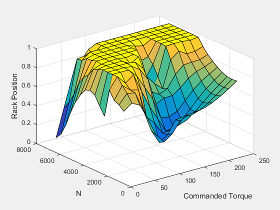
The controller commands the EGR valve area percent and VGT rack position. Changing the VGT rack position modifies the turbine flow characteristics. At low-requested torques, the rack position can reduce the exhaust back pressure, resulting in a low turbocharger speed and boost pressure. When the commanded fuel requires additional air mass flow, the rack position is set to close the turbocharger vanes, increasing the turbocharger speed and intake manifold boost pressure.
The variable geometry turbocharger (VGT) rack position lookup table is a function of commanded torque and engine speed
where:
RPcmd is VGT rack position command, in percent.
Trqcmd is commanded engine torque, in N·m.
N is engine speed, in rpm.
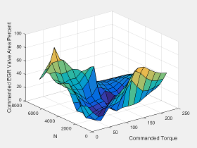
The commanded exhaust gas recirculation (EGR) valve area percent lookup table is a function of commanded torque and engine speed
where:
EGRcmd is commanded EGR valve area percent, in percent.
Trqcmd is commanded engine torque, in N·m.
N is engine speed, in rpm.
To initiate combustion, a CI engine injects fuel directly into the combustion chamber. After the injection, the fuel spontaneously ignites, increasing cylinder pressure. The total mass of the injected fuel and main injection timing determines the torque production.
Assuming constant fuel rail pressure, the CI controller commands the injector pulse-width based on the total requested fuel mass:
The equation uses these variables.
Fuel injector pulse-width | |
| Sinj | Fuel injector slope |
| Fcmd,tot | Commanded total fuel mass per injection |
| MAINSOI | Main start-of-injection timing |
| N | Engine speed |
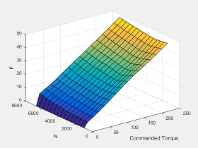
The commanded total fuel mass per injection table is a function of the torque command and engine speed
where:
Fcmd,tot = F is commanded total fuel mass per injection, in mg per cylinder.
Trqcmd is commanded engine torque, in N·m.
N is engine speed, in rpm.
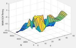
The main start-of-injection (SOI) timing lookup table is a function of commanded fuel mass and engine speed
where:
MAINSOI is the main start-of-injection timing, in degrees crank angle after top dead center (degATDC).
Fcmd,tot = F is commanded fuel mass, in mg per injection.
N is engine speed, in rpm.
When the commanded torque is below a threshold value, the idle speed controller regulates the engine speed.
| If | Idle Speed Controller |
|---|---|
| Trqcmd,input < Trqidlecmd,enable | Enabled |
| Trqidlecmd,enable ≤ Trqcmd,input | Not enabled |
The idle speed controller uses a discrete PI controller to regulate the target idle speed by commanding a torque.
The PI controller uses this transfer function:
The idle speed commanded torque must be less than the maximum commanded torque:
0 ≤ Trqidlecomd ≤Trqidlecmd,max
Idle speed control is active under these conditions. If the commanded input torque drops below the threshold for enabling the idle speed controller (Trqcmd,input < Trqidlecmd,enable), the commanded engine torque is given by:
Trqcmd = max(Trqcmd,input,Trqidlecmd).
The equations use these variables.
| Trqcmd | Commanded engine torque |
| Trqcmd,input | Input commanded engine torque |
| Trqidlecmd,enable | Threshold for enabling idle speed controller |
| Trqidlecmd | Idle speed controller commanded torque |
| Trqidlecmd,max | Maximum commanded torque |
| Nidle | Base idle speed |
| Kp,idle | Idle speed controller proportional gain |
| Ki,idle | Idle speed controller integral gain |
To prevent over revving the engine, the block implements an engine speed limit controller that limits the engine speed to the value specified by the Rev-limiter speed threshold parameter on the Controls > Idle Speed tab.
If the engine speed, N, exceeds the engine speed limit, Nlim, the block sets the commanded engine torque to 0.
To smoothly transition the torque command to 0 as the engine speed approaches the speed limit, the block implements a lookup table multiplier. The lookup table multiplies the torque command by a value that ranges from 0 (engine speed exceeds limit) to 1 (engine speed does not exceed the limit).
Estimator
Using the CI Core Engine block, the CI
Controller block estimates the air mass flow rate, EGR valve
mass flow, exhaust back-pressure, engine torque, AFR, and exhaust
temperature from sensor feedback. The Info port
provides the estimated values, but block does not use them to determine
the open-loop engine actuator commands.
To calculate the air mass flow, the compression-ignition (CI) engine uses the CI Engine Speed-Density Air Mass Flow Model. The speed-density model uses the speed-density equation to calculate the engine air mass flow, relating the engine intake port mass flow to the intake manifold pressure, intake manifold temperature, and engine speed.
To calculate the estimated exhaust gas recirculation (EGR) valve mass flow, the block calculates the EGR flow that would occur at standard temperature and pressure conditions, and then corrects the flow to actual temperature and pressure conditions. The block EGR calculation uses estimated exhaust back-pressure, estimated exhaust temperature, standard temperature, and standard pressure.
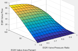
The standard exhaust gas recirculation (EGR) mass flow is a lookup table that is a function of the standard flow pressure ratio and EGR valve flow area
where:
is the standard EGR valve mass flow, in g/s.
Pexh,est is the estimated exhaust back-pressure, in Pa.
MAP is the cycle average intake manifold absolute pressure, in Pa.
EGRap is the measured EGR valve area, in percent.
The equations use these variables.
Estimated EGR valve mass flow | |
Standard EGR valve mass flow | |
Standard pressure | |
Standard temperature | |
Texh,est | Estimated exhaust manifold gas temperature |
| MAP | Measured cycle average intake manifold absolute pressure |
Pexh,est | Estimated exhaust back-pressure |
Absolute ambient pressure | |
| EGRap | Measured EGR valve area percent |
To estimate the EGR valve mass flow, the block requires an estimate of the exhaust back-pressure. To estimate the exhaust back-pressure, the block uses the ambient pressure and the turbocharger pressure ratio.
For the turbocharger pressure ration calculation, the block uses two lookup tables. The first lookup table determines the approximate turbocharger pressure ratio as a function of turbocharger mass flow and corrected turbocharger speed. Using a second lookup table, the block corrects the approximate turbocharger pressure ratio for VGT rack position.
The equations use these variables.
Estimated EGR valve mass flow | |
Standard EGR valve mass flow | |
Estimated intake port mass flow rate | |
| Standard air mass flow | |
| EGRap | Measured EGR valve area |
| MAP | Measured cycle average intake manifold absolute pressure |
| MAT | Measured cycle average intake manifold gas absolute temperature |
Standard pressure | |
Standard temperature | |
Texh,est | Estimated exhaust manifold gas temperature |
Prvgtcorr | Turbocharger pressure ratio correction for VGT rack position |
Prturbo | Turbocharger pressure ratio |
Pexh,est | Estimated exhaust back-pressure |
Absolute ambient pressure | |
| Nvgtcorr | Corrected turbocharger speed |
| VGTpos | Measured VGT rack position |
The exhaust-back pressure calculation uses these lookup tables:
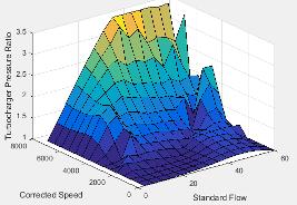
The turbocharger pressure ratio, corrected for variable geometry turbocharger (VGT) speed, is a lookup table that is a function of the standard air mass flow and corrected turbocharger speed, , where:
Prturbo is the turbocharger pressure ratio, corrected for VGT speed.
is the standard air mass flow, in g/s.
Nvgtcorr is the corrected turbocharger speed, in rpm/K^(1/2).
To calculate the standard air mass flow through the turbocharger, the block uses conservation of mass, the estimated intake port, and EGR mass flows (from the last estimated calculation). The calculation assumes negligible exhaust manifold filling dynamics.
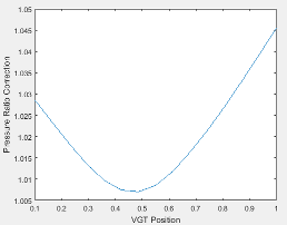
The variable geometry turbocharger pressure ratio correction is a function of the rack position, Prvgtcorr= ƒ(VGTpos), where:
Prvgtcorr is the turbocharger pressure ratio correction.
VGTpos is the variable geometry turbocharger (VGT) rack position.
To calculate the engine torque, you can configure the block to use either of these torque models.
| Brake Torque Model | Description |
|---|---|
| CI Engine Torque Structure Model |
The CI core engine torque structure model determines the engine torque by reducing the maximum engine torque potential as these engine conditions vary from nominal:
To account for the effect of post-inject fuel on torque, the model uses a calibrated torque offset table. |
| CI Engine Simple Torque Model | For the simple engine torque calculation, the CI engine uses a torque lookup table map that is a function of engine speed and injected fuel mass. |
The exhaust temperature calculation depends on the torque model. For both torque models, the block implements lookup tables.
Torque Model | Description | Equations |
|---|---|---|
| Exhaust temperature lookup table is a function of the injected fuel mass and engine speed. |
|
Torque Structure |
The nominal exhaust temperature, Texhnom, is a product of these exhaust temperature efficiencies:
The exhaust temperature, Texhnom, is offset by a post temperature effect, ΔTpost, that accounts for post and late injections during the expansion and exhaust strokes. |
|
The equations use these variables.
F | Compression stroke injected fuel mass |
N | Engine speed |
Texh | Exhaust manifold gas temperature |
Texhopt | Optimal exhaust manifold gas temperature |
| ΔTpost | Post injection temperature effect |
| Texhnom | Nominal exhaust temperature |
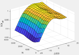
SOIexhteff | Main SOI exhaust temperature efficiency multiplier |
ΔSOI | Main SOI timing relative to optimal timing |
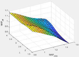
MAPexheff | Intake manifold gas pressure exhaust temperature efficiency multiplier |
MAPratio | Intake manifold gas pressure ratio relative to optimal pressure ratio |
λ | Intake manifold gas lambda |
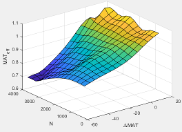
MATexheff | Intake manifold gas temperature exhaust temperature efficiency multiplier |
ΔMAT | Intake manifold gas temperature relative to optimal temperature |
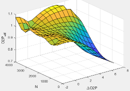
O2Pexheff | Intake manifold gas oxygen exhaust temperature efficiency multiplier |
ΔO2P | Intake gas oxygen percent relative to optimal |
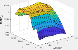
FUELPexheff | Fuel rail pressure exhaust temperature efficiency multiplier |
ΔFUELP | Fuel rail pressure relative to optimal |
The measured engine speed and fuel injector pulse-width determine the commanded fuel mass flow rate:
The commanded total fuel mass flow and estimated port mass flow rates determine the estimated AFR:
The equations use these variables.
Fuel injector pulse-width | |
| AFRest | Estimated air-fuel ratio |
Commanded fuel mass flow rate | |
Fuel injector slope | |
| N | Engine speed |
| Ncyl | Number of engine cylinders |
| Cps | Crankshaft revolutions per power stroke, rev/stroke |
Total estimated engine air mass flow at intake ports |
Examples

Build Conventional Vehicle Model
Build a vehicle with an internal combustion engine using the conventional vehicle reference application.

Calibrate, Validate, and Optimize CI Engine with Dynamometer Test Harness
Simulate a compression-ignition (CI) engine and controller under a dynamometer test harness using the CI engine dynamometer reference application.
Ports
Input
Output
Parameters
Controls
Air - EGR
The commanded exhaust gas recirculation (EGR) valve area percent lookup table is a function of commanded torque and engine speed
where:
EGRcmd is commanded EGR valve area percent, in percent.
Trqcmd is commanded engine torque, in N·m.
N is engine speed, in rpm.
Programmatic Use
To set the block parameter value programmatically, use
the set_param function.
To get the block parameter value
programmatically, use the get_param function.
| Parameter: | f_egrcmd |
| Values: | array |
| Data Types: | double |
Air - VGR
The variable geometry turbocharger (VGT) rack position lookup table is a function of commanded torque and engine speed
where:
RPcmd is VGT rack position command, in percent.
Trqcmd is commanded engine torque, in N·m.
N is engine speed, in rpm.
Programmatic Use
To set the block parameter value programmatically, use
the set_param function.
To get the block parameter value
programmatically, use the get_param function.
| Parameter: | f_rpcmd |
| Values: | array |
| Data Types: | double |
Fuel
The commanded total fuel mass per injection table is a function of the torque command and engine speed
where:
Fcmd,tot = F is commanded total fuel mass per injection, in mg per cylinder.
Trqcmd is commanded engine torque, in N·m.
N is engine speed, in rpm.
Programmatic Use
To set the block parameter value programmatically, use
the set_param function.
To get the block parameter value
programmatically, use the get_param function.
| Parameter: | f_fcmd_tot |
| Values: | array |
| Data Types: | double |
The main start-of-injection (SOI) timing lookup table is a function of commanded fuel mass and engine speed
where:
MAINSOI is the main start-of-injection timing, in degrees crank angle after top dead center (degATDC).
Fcmd,tot = F is commanded fuel mass, in mg per injection.
N is engine speed, in rpm.
Programmatic Use
To set the block parameter value programmatically, use
the set_param function.
To get the block parameter value
programmatically, use the get_param function.
| Parameter: | f_main_soi |
| Values: | array |
| Data Types: | double |
Fuel main injection timing fuel breakpoints, in mg per injection.
Programmatic Use
To set the block parameter value programmatically, use
the set_param function.
To get the block parameter value
programmatically, use the get_param function.
| Parameter: | f_main_soi_f_bpt |
| Values: | vector |
| Data Types: | double |
Idle Speed
Torque to enable the idle speed controller, Trqidlecmd,enable, in N·m.
Programmatic Use
To set the block parameter value programmatically, use
the set_param function.
To get the block parameter value
programmatically, use the get_param function.
| Parameter: | Trq_idlecmd_enable |
| Values: | 1 (default) | scalar |
| Data Types: | double |
Maximum idle controller commanded torque, Trqidlecmd,max, in N·m.
Programmatic Use
To set the block parameter value programmatically, use
the set_param function.
To get the block parameter value
programmatically, use the get_param function.
| Parameter: | Trq_idlecmd_max |
| Values: | 50 (default) | scalar |
| Data Types: | double |
Proportional gain for idle speed control, Kp,idle, in N·m/rpm.
Programmatic Use
To set the block parameter value programmatically, use
the set_param function.
To get the block parameter value
programmatically, use the get_param function.
| Parameter: | Kp_idle |
| Values: | 0.05 (default) | scalar |
| Data Types: | double |
Integral gain for idle speed control, Ki,idle, in N·m/(rpm·s).
Programmatic Use
To set the block parameter value programmatically, use
the set_param function.
To get the block parameter value
programmatically, use the get_param function.
| Parameter: | Ki_idle |
| Values: | 0.2 (default) | scalar |
| Data Types: | double |
Engine speed limit, Nlim, in rpm.
If the engine speed, N, exceeds the engine speed limit, Nlim, the block sets the commanded engine torque to 0.
To smoothly transition the torque command to 0 as the engine speed approaches the speed limit, the block implements a lookup table multiplier. The lookup table multiplies the torque command by a value that ranges from 0 (engine speed exceeds limit) to 1 (engine speed does not exceed the limit).
Programmatic Use
To set the block parameter value programmatically, use
the set_param function.
To get the block parameter value
programmatically, use the get_param function.
| Parameter: | EngRevLim |
| Values: | 6000 (default) | scalar |
| Data Types: | double |
Stop-Start
Select to enable the engine stop-start logic. Selecting this option will activate additional parameters to modify the behavior of the Engine Stop-Start block.
Programmatic Use
To set the block parameter value programmatically, use
the set_param function.
To get the block parameter value
programmatically, use the get_param function.
| Parameter: | ESSEnable |
| Values: | off (default) | on |
| Data Types: | character vector |
Select to add a port to the engine controller block which enables or disables the stop-start logic.
Programmatic Use
To set the block parameter value programmatically, use
the set_param function.
To get the block parameter value
programmatically, use the get_param function.
| Parameter: | ESSExternalPortEnable |
| Values: | off (default) | on |
| Data Types: | character vector |
Dependencies
To enable this parameter, on the Stop-Start tab, select Enable Engine Stop-Start.
Engine stop time for the stop-start logic, in s.
Programmatic Use
To set the block parameter value programmatically, use
the set_param function.
To get the block parameter value
programmatically, use the get_param function.
| Parameter: | EngStopTime |
| Values: | 5 (default) | scalar |
| Data Types: | double |
Dependencies
To enable this parameter, on the Stop-Start tab, select Enable Engine Stop-Start.
Catalyst light off time for the stop-start logic, in s.
Programmatic Use
To set the block parameter value programmatically, use
the set_param function.
To get the block parameter value
programmatically, use the get_param function.
| Parameter: | CatLightOffTime |
| Values: | 0 (default) | scalar |
| Data Types: | double |
Dependencies
To enable this parameter, on the Stop-Start tab, select Enable Engine Stop-Start.
Sample time for the stop-start logic, in s.
Programmatic Use
To set the block parameter value programmatically, use
the set_param function.
To get the block parameter value
programmatically, use the get_param function.
| Parameter: | Ts |
| Values: | 0.01 (default) | scalar |
| Data Types: | double |
Dependencies
To enable this parameter, on the Stop-Start tab, select Enable Engine Stop-Start.
Estimation
Air
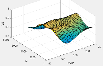
The volumetric efficiency lookup table is a function of the intake manifold absolute pressure at intake valve closing (IVC) and engine speed
where:
is engine volumetric efficiency, dimensionless.
MAP is intake manifold absolute pressure, in KPa.
N is engine speed, in rpm.
Programmatic Use
To set the block parameter value programmatically, use
the set_param function.
To get the block parameter value
programmatically, use the get_param function.
| Parameter: | f_nv |
| Values: | array |
| Data Types: | double |
Intake manifold pressure breakpoints for speed-density volumetric efficiency lookup table, in KPa.
Programmatic Use
To set the block parameter value programmatically, use
the set_param function.
To get the block parameter value
programmatically, use the get_param function.
| Parameter: | f_nv_prs_bpt |
| Values: | vector |
| Data Types: | double |
Engine speed breakpoints for speed-density volumetric efficiency lookup table, in rpm.
Programmatic Use
To set the block parameter value programmatically, use
the set_param function.
To get the block parameter value
programmatically, use the get_param function.
| Parameter: | f_nv_n_bpt |
| Values: | vector |
| Data Types: | double |
The standard exhaust gas recirculation (EGR) mass flow is a lookup table that is a function of the standard flow pressure ratio and EGR valve flow area
where:
is the standard EGR valve mass flow, in g/s.
Pexh,est is the estimated exhaust back-pressure, in Pa.
MAP is the cycle average intake manifold absolute pressure, in Pa.
EGRap is the measured EGR valve area, in percent.
Programmatic Use
To set the block parameter value programmatically, use
the set_param function.
To get the block parameter value
programmatically, use the get_param function.
| Parameter: | f_egr_stdflow |
| Values: | vector |
| Data Types: | double |
EGR valve standard flow pressure ratio breakpoints, dimensionless.
Programmatic Use
To set the block parameter value programmatically, use
the set_param function.
To get the block parameter value
programmatically, use the get_param function.
| Parameter: | f_egr_stdflow_pr_bpt |
| Values: | vector |
| Data Types: | double |
EGR valve standard flow area percent breakpoints, in percent.
Programmatic Use
To set the block parameter value programmatically, use
the set_param function.
To get the block parameter value
programmatically, use the get_param function.
| Parameter: | f_egr_stdflow_egrap_bpt |
| Values: | vector |
| Data Types: | double |
The turbocharger pressure ratio, corrected for variable geometry turbocharger (VGT) speed, is a lookup table that is a function of the standard air mass flow and corrected turbocharger speed, , where:
Prturbo is the turbocharger pressure ratio, corrected for VGT speed.
is the standard air mass flow, in g/s.
Nvgtcorr is the corrected turbocharger speed, in rpm/K^(1/2).
Programmatic Use
To set the block parameter value programmatically, use
the set_param function.
To get the block parameter value
programmatically, use the get_param function.
| Parameter: | f_turbo_pr |
| Values: | array |
| Data Types: | double |
Turbocharger pressure ratio standard flow breakpoints, in g/s.
Programmatic Use
To set the block parameter value programmatically, use
the set_param function.
To get the block parameter value
programmatically, use the get_param function.
| Parameter: | f_turbo_pr_stdflow_bpt |
| Values: | vector |
| Data Types: | double |
Turbocharger pressure ratio corrected speed breakpoints, in rpm/K^(1/2).
Programmatic Use
To set the block parameter value programmatically, use
the set_param function.
To get the block parameter value
programmatically, use the get_param function.
| Parameter: | f_turbo_pr_corrspd_bpt |
| Values: | vector |
| Data Types: | double |
The variable geometry turbocharger pressure ratio correction is a function of the rack position, Prvgtcorr= ƒ(VGTpos), where:
Prvgtcorr is the turbocharger pressure ratio correction.
VGTpos is the variable geometry turbocharger (VGT) rack position.
Programmatic Use
To set the block parameter value programmatically, use
the set_param function.
To get the block parameter value
programmatically, use the get_param function.
| Parameter: | f_turbo_pr_vgtposcorr |
| Values: | array |
| Data Types: | double |
Turbocharger pressure ratio VGT position correction breakpoints, dimensionless.
Programmatic Use
To set the block parameter value programmatically, use
the set_param function.
To get the block parameter value
programmatically, use the get_param function.
| Parameter: | f_nv_n_bpt |
| Values: | vector |
| Data Types: | double |
Torque - Simple Torque Lookup
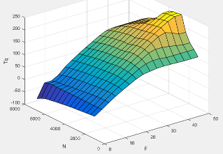
For the simple torque lookup table model, the CI engine uses a lookup table is a function of engine speed and injected fuel mass, , where:
Tq = Tbrake is engine brake torque after accounting for engine mechanical and pumping friction effects, in N·m.
F is injected fuel mass, in mg per injection.
N is engine speed, in rpm.
Programmatic Use
To set the block parameter value programmatically, use
the set_param function.
To get the block parameter value
programmatically, use the get_param function.
| Parameter: | f_tq_nf |
| Values: | array |
| Data Types: | double |
Dependencies
To enable this parameter, for Torque model, select
Simple Torque Lookup.
Torque - Torque Structure
Engine speed breakpoints, in rpm.
Programmatic Use
To set the block parameter value programmatically, use
the set_param function.
To get the block parameter value
programmatically, use the get_param function.
| Parameter: | f_tqs_n_bpt |
| Values: | vector |
| Data Types: | double |
Dependencies
To enable this parameter, for Torque model, select
Torque Structure.
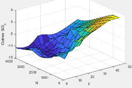
The optimal main start of injection (SOI) timing lookup table, ƒSOIc, is a function of the engine speed and injected fuel mass, SOIc = ƒSOIc(F,N), where:
SOIc is optimal SOI timing, in degATDC.
F is compression stroke injected fuel mass, in mg per injection.
N is engine speed, in rpm.
Programmatic Use
To set the block parameter value programmatically, use
the set_param function.
To get the block parameter value
programmatically, use the get_param function.
| Parameter: | f_tqs_mainsoi |
| Values: | array |
| Data Types: | double |
Dependencies
To enable this parameter, for Torque model, select
Torque Structure.
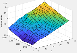
The optimal intake manifold gas pressure lookup table, ƒMAP, is a function of the engine speed and injected fuel mass, MAP = ƒMAP(F,N), where:
MAP is optimal intake manifold gas pressure, in Pa.
F is compression stroke injected fuel mass, in mg per injection.
N is engine speed, in rpm.
Programmatic Use
To set the block parameter value programmatically, use
the set_param function.
To get the block parameter value
programmatically, use the get_param function.
| Parameter: | f_tqs_map |
| Values: | array |
| Data Types: | double |
Dependencies
To enable this parameter, for Torque model, select
Torque Structure.
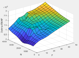
The optimal exhaust manifold gas pressure lookup table, ƒEMAP, is a function of the engine speed and injected fuel mass, EMAP = ƒEMAP(F,N), where:
EMAP is optimal exhaust manifold gas pressure, in Pa.
F is compression stroke injected fuel mass, in mg per injection.
N is engine speed, in rpm.
Programmatic Use
To set the block parameter value programmatically, use
the set_param function.
To get the block parameter value
programmatically, use the get_param function.
| Parameter: | f_tqs_emap |
| Values: | array |
| Data Types: | double |
Dependencies
To enable this parameter, for Torque model, select
Torque Structure.
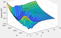
The optimal intake manifold gas temperature lookup table, ƒMAT, is a function of the engine speed and injected fuel mass, MAT = ƒMAT(F,N), where:
MAT is optimal intake manifold gas temperature, in K.
F is compression stroke injected fuel mass, in mg per injection.
N is engine speed, in rpm.
Programmatic Use
To set the block parameter value programmatically, use
the set_param function.
To get the block parameter value
programmatically, use the get_param function.
| Parameter: | f_tqs_mat |
| Values: | array |
| Data Types: | double |
Dependencies
To enable this parameter, for Torque model, select
Torque Structure.
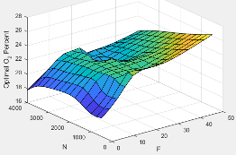
The optimal intake gas oxygen percent lookup table, ƒO2, is a function of the engine speed and injected fuel mass, O2PCT = ƒO2(F,N), where:
O2PCT is optimal intake gas oxygen, in percent.
F is compression stroke injected fuel mass, in mg per injection.
N is engine speed, in rpm.
Programmatic Use
To set the block parameter value programmatically, use
the set_param function.
To get the block parameter value
programmatically, use the get_param function.
| Parameter: | f_tqs_o2pct |
| Values: | array |
| Data Types: | double |
Dependencies
To enable this parameter, for Torque model, select
Torque Structure.
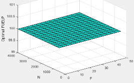
The optimal fuel rail pressure lookup table, ƒfuelp, is a function of the engine speed and injected fuel mass, FUELP = ƒfuelp(F,N), where:
FUELP is optimal fuel rail pressure, in MPa.
F is compression stroke injected fuel mass, in mg per injection.
N is engine speed, in rpm.
Programmatic Use
To set the block parameter value programmatically, use
the set_param function.
To get the block parameter value
programmatically, use the get_param function.
| Parameter: | f_tqs_fuelpress |
| Values: | array |
| Data Types: | double |
Dependencies
To enable this parameter, for Torque model, select
Torque Structure.
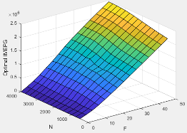
The optimal gross indicated mean effective pressure lookup table, ƒimepg, is a function of the engine speed and injected fuel mass, IMEPG = ƒimepg(F,N), where:
IMEPG is optimal gross indicated mean effective pressure, in Pa.
F is compression stroke injected fuel mass, in mg per injection.
N is engine speed, in rpm.
Programmatic Use
To set the block parameter value programmatically, use
the set_param function.
To get the block parameter value
programmatically, use the get_param function.
| Parameter: | f_tqs_imepg |
| Values: | array |
| Data Types: | double |
Dependencies
To enable this parameter, for Torque model, select
Torque Structure.
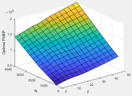
The optimal friction mean effective pressure lookup table, ƒfmep, is a function of the engine speed and injected fuel mass, FMEP = ƒfmep(F,N), where:
FMEP is optimal friction mean effective pressure, in Pa.
F is compression stroke injected fuel mass, in mg per injection.
N is engine speed, in rpm.
Programmatic Use
To set the block parameter value programmatically, use
the set_param function.
To get the block parameter value
programmatically, use the get_param function.
| Parameter: | f_tqs_fmep |
| Values: | array |
| Data Types: | double |
Dependencies
To enable this parameter, for Torque model, select
Torque Structure.
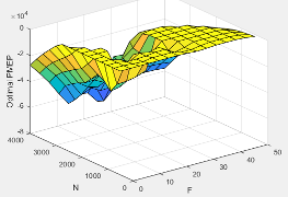
The optimal pumping mean effective pressure lookup table, ƒpmep, is a function of the engine speed and injected fuel mass, PMEP = ƒpmep(F,N), where:
PMEP is optimal pumping mean effective pressure, in Pa.
F is compression stroke injected fuel mass, in mg per injection.
N is engine speed, in rpm.
Programmatic Use
To set the block parameter value programmatically, use
the set_param function.
To get the block parameter value
programmatically, use the get_param function.
| Parameter: | f_tqs_pmep |
| Values: | array |
| Data Types: | double |
Dependencies
To enable this parameter, for Torque model, select
Torque Structure.
Friction multiplier as a function of temperature, dimensionless.
Programmatic Use
To set the block parameter value programmatically, use
the set_param function.
To get the block parameter value
programmatically, use the get_param function.
| Parameter: | f_tqs_fric_temp_mod |
| Values: | array |
| Data Types: | double |
Dependencies
To enable this parameter, for Torque model, select
Torque Structure.
Friction multiplier temperature breakpoints, in K.
Programmatic Use
To set the block parameter value programmatically, use
the set_param function.
To get the block parameter value
programmatically, use the get_param function.
| Parameter: | f_tqs_fric_temp_bpt |
| Values: | vector |
| Data Types: | double |
Dependencies
To enable this parameter, for Torque model, select
Torque Structure.
The main start of injection (SOI) timing efficiency multiplier lookup table, ƒSOIeff, is a function of the engine speed and main SOI timing relative to optimal timing, SOIeff = ƒSOIeff(ΔSOI,N), where:
SOIeff is main SOI timing efficiency multiplier, dimensionless.
ΔSOI is main SOI timing relative to optimal timing, in degBTDC.
N is engine speed, in rpm.
Programmatic Use
To set the block parameter value programmatically, use
the set_param function.
To get the block parameter value
programmatically, use the get_param function.
| Parameter: | f_tqs_mainsoi_eff |
| Values: | array |
| Data Types: | double |
Dependencies
To enable this parameter, for Torque model, select
Torque Structure.
Main start of injection timing relative to optimal timing breakpoints, in degBTDC.
Programmatic Use
To set the block parameter value programmatically, use
the set_param function.
To get the block parameter value
programmatically, use the get_param function.
| Parameter: | f_tqs_mainsoi_delta_bpt |
| Values: | vector |
| Data Types: | double |
Dependencies
To enable this parameter, for Torque model, select
Torque Structure.
The intake manifold gas pressure efficiency multiplier lookup table, ƒMAPeff, is a function of the intake manifold gas pressure ratio relative to optimal pressure ratio and lambda, MAPeff = ƒMAPeff(MAPratio,λ), where:
MAPeff is intake manifold gas pressure efficiency multiplier, dimensionless.
MAPratio is intake manifold gas pressure ratio relative to optimal pressure ratio, dimensionless.
λ is intake manifold gas lambda, dimensionless.
Programmatic Use
To set the block parameter value programmatically, use
the set_param function.
To get the block parameter value
programmatically, use the get_param function.
| Parameter: | f_tqs_map_eff |
| Values: | array |
| Data Types: | double |
Dependencies
To enable this parameter, for Torque model, select
Torque Structure.
Intake manifold gas pressure ratio relative to optimal pressure ratio breakpoints, dimensionless.
Programmatic Use
To set the block parameter value programmatically, use
the set_param function.
To get the block parameter value
programmatically, use the get_param function.
| Parameter: | f_tqs_map_ratio_bpt |
| Values: | vector |
| Data Types: | double |
Dependencies
To enable this parameter, for Torque model, select
Torque Structure.
Intake manifold gas lambda breakpoints, dimensionless.
Programmatic Use
To set the block parameter value programmatically, use
the set_param function.
To get the block parameter value
programmatically, use the get_param function.
| Parameter: | f_tqs_lambda_bpt |
| Values: | vector |
| Data Types: | double |
Dependencies
To enable this parameter, for Torque model, select
Torque Structure.
The intake manifold gas temperature efficiency multiplier lookup table, ƒMATeff, is a function of the engine speed and intake manifold gas temperature relative to optimal temperature, MATeff = ƒMATeff(ΔMAT,N), where:
MATeff is intake manifold gas temperature efficiency multiplier, dimensionless.
ΔMAT is intake manifold gas temperature relative to optimal temperature, in K.
N is engine speed, in rpm.
Programmatic Use
To set the block parameter value programmatically, use
the set_param function.
To get the block parameter value
programmatically, use the get_param function.
| Parameter: | f_tqs_mat_eff |
| Values: | array |
| Data Types: | double |
Dependencies
To enable this parameter, for Torque model, select
Torque Structure.
Intake manifold gas temperature relative to optimal gas temperature breakpoints, in K.
Programmatic Use
To set the block parameter value programmatically, use
the set_param function.
To get the block parameter value
programmatically, use the get_param function.
| Parameter: | f_tqs_mat_delta_bpt |
| Values: | vector |
| Data Types: | double |
Dependencies
To enable this parameter, for Torque model, select
Torque Structure.
The intake manifold gas oxygen efficiency multiplier lookup table, ƒO2Peff, is a function of the engine speed and intake manifold gas oxygen percent relative to optimal, O2Peff = ƒO2Peff(ΔO2P,N), where:
O2Peff is intake manifold gas oxygen efficiency multiplier, dimensionless.
ΔO2P is intake gas oxygen percent relative to optimal, in percent.
N is engine speed, in rpm.
Programmatic Use
To set the block parameter value programmatically, use
the set_param function.
To get the block parameter value
programmatically, use the get_param function.
| Parameter: | f_tqs_o2pct_eff |
| Values: | array |
| Data Types: | double |
Dependencies
To enable this parameter, for Torque model, select
Torque Structure.
Intake gas oxygen percent relative to optimal breakpoints, in percent.
Programmatic Use
To set the block parameter value programmatically, use
the set_param function.
To get the block parameter value
programmatically, use the get_param function.
| Parameter: | f_tqs_o2pct_delta_bpt |
| Values: | vector |
| Data Types: | double |
Dependencies
To enable this parameter, for Torque model, select
Torque Structure.
The fuel rail pressure efficiency multiplier lookup table, ƒFUELPeff, is a function of the engine speed and fuel rail pressure relative to optimal breakpoints, FUELPeff = ƒFUELPeff(ΔFUELP,N), where:
FUELPeff is fuel rail pressure efficiency multiplier, dimensionless.
ΔFUELP is fuel rail pressure relative to optimal, in MPa.
N is engine speed, in rpm.
Programmatic Use
To set the block parameter value programmatically, use
the set_param function.
To get the block parameter value
programmatically, use the get_param function.
| Parameter: | f_tqs_fuelpress_eff |
| Values: | array |
| Data Types: | double |
Dependencies
To enable this parameter, for Torque model, select
Torque Structure.
Fuel rail pressure relative to optimal breakpoints, in MPa.
Programmatic Use
To set the block parameter value programmatically, use
the set_param function.
To get the block parameter value
programmatically, use the get_param function.
| Parameter: | f_tqs_fuelpress_delta_bpt |
| Values: | vector |
| Data Types: | double |
Dependencies
To enable this parameter, for Torque model, select
Torque Structure.
Fuel mass injection type identifier, dimensionless.
In the CI Core Engine and CI Controller blocks, you can represent multiple injections with the start of injection (SOI) and fuel mass inputs to the model. To specify the type of injection, use the Fuel mass injection type identifier parameter.
| Type of Injection | Parameter Value |
|---|---|
Pilot |
|
Main |
|
Post |
|
Passed |
|
The model considers Passed fuel injections and fuel injected
later than a threshold to be unburned fuel. Use the Maximum start of injection angle
for burned fuel, f_tqs_f_burned_soi_limit parameter to specify the
threshold.
Programmatic Use
To set the block parameter value programmatically, use
the set_param function.
To get the block parameter value
programmatically, use the get_param function.
| Parameter: | f_tqs_f_inj_type |
| Values: | 0 (default) | scalar |
| Data Types: | double |
Dependencies
To enable this parameter, for Torque model, select
Torque Structure.
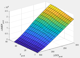
The indicated mean effective pressure post inject correction lookup table, ƒIMEPpost, is a function of the engine speed and fuel rail pressure relative to optimal breakpoints, ΔIMEPpost = ƒIMEPpost(ΔSOIpost,Fpost), where:
ΔIMEPpost is indicated mean effective pressure post inject correction, in Pa.
ΔSOIpost is indicated mean effective pressure post inject start of inject timing centroid, in degATDC.
Fpost is indicated mean effective pressure post inject mass sum, in mg per injection.
Programmatic Use
To set the block parameter value programmatically, use
the set_param function.
To get the block parameter value
programmatically, use the get_param function.
| Parameter: | f_tqs_imep_post_corr |
| Values: | array |
| Data Types: | double |
Dependencies
To enable this parameter, for Torque model, select
Torque Structure.
Indicated mean effective pressure post inject mass sum breakpoints, in mg per injection.
Programmatic Use
To set the block parameter value programmatically, use
the set_param function.
To get the block parameter value
programmatically, use the get_param function.
| Parameter: | f_tqs_f_post_sum_bpt |
| Values: | vector |
| Data Types: | double |
Dependencies
To enable this parameter, for Torque model, select
Torque Structure.
Indicated mean effective pressure post inject start of inject timing centroid breakpoints, in degATDC.
Programmatic Use
To set the block parameter value programmatically, use
the set_param function.
To get the block parameter value
programmatically, use the get_param function.
| Parameter: | f_tqs_soi_post_cent_bpt |
| Values: | vector |
| Data Types: | double |
Dependencies
To enable this parameter, for Torque model, select
Torque Structure.
Maximum start of injection angle for burned fuel, in degATDC.
Programmatic Use
To set the block parameter value programmatically, use
the set_param function.
To get the block parameter value
programmatically, use the get_param function.
| Parameter: | f_tqs_f_bpt |
| Values: | 500 (default) | scalar |
| Data Types: | double |
Dependencies
To enable this parameter, for Torque model, select
Torque Structure.
Exhaust
Exhaust Temperature - Simple Torque Lookup
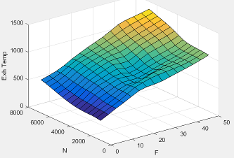
The lookup table for the exhaust temperature is a function of injected fuel mass and engine speed
where:
is exhaust temperature, in K.
F is injected fuel mass, in mg per injection.
N is engine speed, in rpm.
Programmatic Use
To set the block parameter value programmatically, use
the set_param function.
To get the block parameter value
programmatically, use the get_param function.
| Parameter: | f_t_exh |
| Values: | array |
| Data Types: | double |
Dependencies
To enable this parameter, for Torque model, select
Simple Torque Lookup.
Engine load breakpoints used for exhaust temperature lookup table, in mg per injection.
Programmatic Use
To set the block parameter value programmatically, use
the set_param function.
To get the block parameter value
programmatically, use the get_param function.
| Parameter: | f_t_exh_f_bpt |
| Values: | vector |
| Data Types: | double |
Dependencies
To enable this parameter, for Torque model, select
Simple Torque Lookup.
Engine speed breakpoints used for exhaust temperature lookup table, in rpm.
Programmatic Use
To set the block parameter value programmatically, use
the set_param function.
To get the block parameter value
programmatically, use the get_param function.
| Parameter: | f_t_exh_n_bpt |
| Values: | vector |
| Data Types: | double |
Dependencies
To enable this parameter, for Torque model, select
Simple Torque Lookup.
Exhaust Temperature - Torque Structure
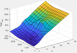
The optimal exhaust manifold gas temperature lookup table, ƒTexh, is a function of the engine speed engine speed and injected fuel mass, Texhopt = ƒTexh(F,N), where:
Texhopt is optimal exhaust manifold gas temperature, in K.
F is compression stroke injected fuel mass, in mg per injection.
N is engine speed, in rpm.
Programmatic Use
To set the block parameter value programmatically, use
the set_param function.
To get the block parameter value
programmatically, use the get_param function.
| Parameter: | f_tqs_exht |
| Values: | array |
| Data Types: | double |
Dependencies
To enable this parameter, for Torque model, select
Torque Structure.
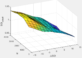
The main start of injection (SOI) timing exhaust temperature efficiency multiplier lookup table, ƒSOIexhteff, is a function of the engine speed engine speed and injected fuel mass, SOIexhteff = ƒSOIexhteff(ΔSOI,N), where:
SOIexhteff is main SOI exhaust temperature efficiency multiplier, dimensionless.
ΔSOI is main SOI timing relative to optimal timing, in degBTDC.
N is engine speed, in rpm.
Programmatic Use
To set the block parameter value programmatically, use
the set_param function.
To get the block parameter value
programmatically, use the get_param function.
| Parameter: | f_tqs_exht_mainsoi_eff |
| Values: | array |
| Data Types: | double |
Dependencies
To enable this parameter, for Torque model, select
Torque Structure.
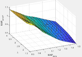
The intake manifold gas pressure exhaust temperature efficiency multiplier lookup table, ƒMAPexheff, is a function of the intake manifold gas pressure ratio relative to optimal pressure ratio and lambda, MAPexheff = ƒMAPexheff(MAPratio,λ), where:
MAPexheff is intake manifold gas pressure exhaust temperature efficiency multiplier, dimensionless.
MAPratio is intake manifold gas pressure ratio relative to optimal pressure ratio, dimensionless.
λ is intake manifold gas lambda, dimensionless.
Programmatic Use
To set the block parameter value programmatically, use
the set_param function.
To get the block parameter value
programmatically, use the get_param function.
| Parameter: | f_tqs_exht_map_eff |
| Values: | array |
| Data Types: | double |
Dependencies
To enable this parameter, for Torque model, select
Torque Structure.
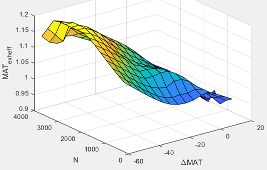
The intake manifold gas temperature exhaust temperature efficiency multiplier lookup table, ƒMATexheff, is a function of the engine speed and intake manifold gas temperature relative to optimal temperature, MATexheff = ƒMATexheff(ΔMAT,N), where:
MATexheff is intake manifold gas temperature exhaust temperature efficiency multiplier, dimensionless.
ΔMAT is intake manifold gas temperature relative to optimal temperature, in K.
N is engine speed, in rpm.
Programmatic Use
To set the block parameter value programmatically, use
the set_param function.
To get the block parameter value
programmatically, use the get_param function.
| Parameter: | f_tqs_exht_mat_eff |
| Values: | array |
| Data Types: | double |
Dependencies
To enable this parameter, for Torque model, select
Torque Structure.
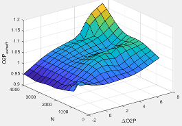
The intake manifold gas oxygen exhaust temperature efficiency multiplier lookup table, ƒO2Pexheff, is a function of the engine speed and intake manifold gas oxygen percent relative to optimal, O2Pexheff = ƒO2Pexheff(ΔO2P,N), where:
O2Pexheff is intake manifold gas oxygen exhaust temperature efficiency multiplier, dimensionless.
ΔO2P is intake gas oxygen percent relative to optimal, in percent.
N is engine speed, in rpm.
Programmatic Use
To set the block parameter value programmatically, use
the set_param function.
To get the block parameter value
programmatically, use the get_param function.
| Parameter: | f_tqs_exht_o2pct_eff |
| Values: | array |
| Data Types: | double |
Dependencies
To enable this parameter, for Torque model, select
Torque Structure.
The fuel rail pressure efficiency exhaust temperature multiplier lookup table, ƒFUELPexheff, is a function of the engine speed and fuel rail pressure relative to optimal breakpoints, FUELPexheff = ƒFUELPexheff(ΔFUELP,N), where:
FUELPexheff is fuel rail pressure exhaust temperature efficiency multiplier, dimensionless.
ΔFUELP is fuel rail pressure relative to optimal, in MPa.
N is engine speed, in rpm.
Programmatic Use
To set the block parameter value programmatically, use
the set_param function.
To get the block parameter value
programmatically, use the get_param function.
| Parameter: | f_tqs_exht_fuelpress_eff |
| Values: | array |
| Data Types: | double |
Dependencies
To enable this parameter, for Torque model, select
Torque Structure.
Post-injection cylinder wall heat loss transfer coefficient, in W/K.
Programmatic Use
To set the block parameter value programmatically, use
the set_param function.
To get the block parameter value
programmatically, use the get_param function.
| Parameter: | f_tqs_exht_post_inj_wall_htc |
| Values: | 0 (default) | scalar |
| Data Types: | double |
Dependencies
To enable this parameter, for Torque model, select
Torque Structure.
References
[1] Heywood, John B. Internal Combustion Engine Fundamentals. New York: McGraw-Hill, 1988.
Extended Capabilities
Version History
Introduced in R2017a