CCSDS RS Encoder
Libraries:
Wireless HDL Toolbox /
Error Detection and Correction
Description
The CCSDS RS Encoder block encodes message symbols into a Reed-Solomon (RS)
codeword according to the Consultative Committee for Space Data Systems (CCSDS) standard [1]. The block accepts message
symbols and a samplecontrol bus and outputs encoded codeword data, a
samplecontrol bus, and a nextFrame signal that
indicates when the block is ready to accept new input message symbols.
The block also supports shortened message lengths. You can use this block in a CCSDS transmitter for satellite communication. The block provides an architecture suitable for HDL code generation and hardware deployment.
Examples

Encode Message into RS Codeword Using CCSDS Standard
Encode message into RS codeword according to CCSDS standard.

Encode and Decode Message with RS Code Using CCSDS Standard
Encode and decode message with RS code according to CCSDS standard.
Ports
Input
Output
Parameters
Algorithms
To form an RS codeword, the CCSDS RS Encoder block generates parity symbols
and appends them to the input message symbols. RS code is a cyclic code, so the input message
symbols are considered message polynomial coefficients and the code generator a generator
polynomial. The generator polynomial divides the message polynomial to obtain a remainder
polynomial that represents parity symbols. This figure shows the implementation of the block
when you set the Message length (k) parameter to 239
and the Interleaving depth (I) parameter to 1. The
encoding circuit in the figure shows the polynomial division logic.
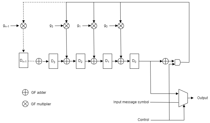
In this figure, g0, g1, g2 g3, and so on up to gn – 1 represent the generator polynomial coefficients and D0, D1, D2, D3, and so on up to Dn – 1 represent registers, where n is equal to 255 – k and k is the Message length (k) parameter value specified on the block mask. The registers store the parity symbols.
The GF multiplier used in the circuit stores all possible GF multiplication outputs for the encoder. These GF multipliers are implemented on the hardware as LUTs. These LUTs consume more hardware resources, so an efficient bit-serial multiplication algorithm [3] is used for the GF multiplier logic. This algorithm leverages the dual-basis representation and makes use of the field trace concept of the Galois field to compute the product. In this process, the values in the registers are updated for every input message symbol. When the last input message symbol of the current frame arrives, the values in the registers are considered parity symbols for the frame.
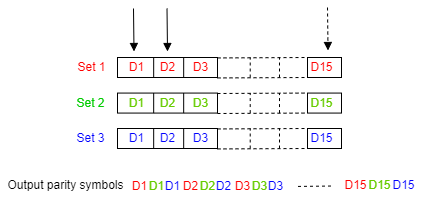
Similarly, if the Interleaving depth (I) parameter is set to
3, three sets of registers are required for each codeword to store the
parity symbols. The number of GF adders and multipliers remains the same, 16, which is equal
to 255 – k. For each input message symbol, the consecutive register sets
Set 1, Set 2, or Set 3 are used in the parity computation. When the last input message symbol
of the current frame arrives, the parity symbols are deinterleaved from each set to form an
output parity sequence as shown in this figure.
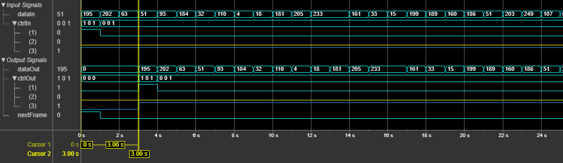
The block captures output bits at valid cycles. The latency of the block is 3 clock cycles.
This figure shows a sample output and latency of the CCSDS RS Encoder
block when you set the Message length (k) and Interleaving
depth (I) parameter values to 223 and 4,
respectively.
References
[1] TM Synchronization and Channel Coding. Recommendation for Space Data System Standards. CCSDS 131.0-B-3. Blue Book. Issue 3. Washington, D.C.: CCSDS, September 2017.
[2] TM Synchronization and Channel Coding. Summary of Concept and Rationale CCSDS 130.1-G-3. Green Book. Issue 3, June 2020.
[3] Hsu, In-Shek , et al. "The VLSI Implementation of a Reed— Solomon Encoder Using Berlekamp’s Bit-Serial Multiplier Algorithm." IEEE Transactions on Computers, vol. C–33, no. 10 (October 1984): 906–11. https://doi.org/10.1109/TC.1984.1676351.
Extended Capabilities
Version History
Introduced in R2022a
See Also
Blocks
Functions
ccsdsRSDecode(Satellite Communications Toolbox) |ccsdsRSEncode(Satellite Communications Toolbox)