Edge Detection and Image Overlay
This example shows how to detect and highlight object edges in a video stream.
The example verifies the behavior of the pixel-stream Edge Detector block, video stream alignment, and overlay, by comparing the results with the same algorithm calculated by the full-frame blocks from the Computer Vision Toolbox™.
This example model provides a hardware-compatible algorithm. You can deploy this algorithm on a board by using an AMD® Zynq® reference design. See Developing Vision Algorithms for Zynq-Based Hardware (SoC Blockset).
Structure of the Example
The EdgeDetectionAndOverlayHDL.slx system is shown below.

The difference in the color of the lines feeding the Full-Frame Behavioral Model and Pixel-Stream HDL Model subsystems indicates the change in the image rate on the streaming branch of the model. This rate transition is because the pixel stream is sent out in the same amount of time as the full video frames and therefore it is transmitted at a higher rate.
Full-Frame Behavioral Model
The following diagram shows the structure of the Full-Frame Behavioral Model subsystem, which employs the frame-based block.

Given that the frame-based Edge Detection (Computer Vision Toolbox) block does not introduce latency, image overlay is performed by weighting the source image and the edge detection output image, and adding them together in a straightforward manner.
One frame of the source video, the edge detection result, and the overlaid image are shown from left to right in the diagram below.

It is a good practice to develop a behavioral system using blocks that process full image frames, the Full-Frame Behavioral Model subsystem in this example, before moving forward to working on an FPGA-targeting design. Such a behavioral model helps verify the video processing design. Later on, it can serve as a reference for verifying the implementation of the algorithm targeted to an FPGA. Specifically, the PSNR (Computer Vision Toolbox) (Peak Signal-to-Noise Ratio) block at the top level of the model compares the results from full-frame processing with those from pixel-stream processing.
Frame To Pixels: Generating a Pixel Stream
The Frame To Pixels block converts a full frame image to pixel stream. To simulate the effect of horizontal and vertical blanking periods found in real life hardware video systems, the active image is augmented with non-image data. For more information on the streaming pixel protocol, see Streaming Pixel Interface. The Frame To Pixels block is configured as shown:
![]()
The Number of components parameter is set to 1 for grayscale image input, and the Video format parameter is 240p to match that of the video source.
In this example, the active video region corresponds to the 240x320 matrix of the dark image from the upstream Corruption block. Six other parameters, namely, Total pixels per line, Total video lines, Starting active line, Ending active line, Front porch, and Back porch specify how many non-image data will be augmented on the four sides of the active video.
Note that the sample time of the Video Source block is determined by the product of Total pixels per line and Total video lines.
Pixel-Stream Edge Detection and Image Overlay
The Pixel-Stream HDL Model subsystem is shown in the diagram below. You can generate HDL code from this subsystem.

Unlike the Edge Detection block in the Full-Frame Behavioral Model, the Edge Detector block from the Vision HDL Toolbox™ models hardware algorithm latency. The latency prevents us from directly weighting and adding two images to obtain the overlaid image. To address this issue, the Pixel Stream Aligner block synchronizes the two pixel streams before the sum.
To properly use the Pixel Stream Aligner block, connect the refPixel and refCtrl ports to the pixel and control bus that are associated with a delayed pixel stream. In this example, due to the latency of the Edge Detector block, the pixel stream coming out of the Edge Detection subsystem is delayed with respect to the input stream. Therefore, the upstream source of refPixel and refCtrl are the pixelOut and ctrlOut signals from the Edge Detection subsystem.
Pixels To Frame: Converting Pixel Stream Back to Full Frame
Frame To Pixels converts a full image frame to pixel stream. The companion Pixels To Frame block converts the pixel stream back to the full frame by using the synchronization signals. Since the output of the Pixels To Frame block is a 2-D matrix of a full image, there is no need to further carry on the bus containing five synchronization signals.
To match the format of the video source, the Number of components and Video format parameters are set at 1 and 240p, respectively, in both the Frame To Pixels and Pixels To Frame blocks.
Verifying the Pixel Stream Processing Design
While building the streaming portion of the design, the PSNR block continuously verifies results against the original full-frame design. The Delay block on the top level of the model time-aligns the 2-D matrices for a fair comparison. During the course of the simulation, the PSNR block should give inf output, indicating that the output image from the Full-Frame Behavioral Model matches the image generated from the stream processing Pixel-Stream HDL Model.
Exploring the Example
The example allows you to experiment with different threshold and alpha values to examine their effect on the quality of the overlaid images. Specifically, two workspace variables thresholdValue and alpha with initial values 7 and 0.8, respectively, are created upon opening the model. You can modify their values using the MATLAB® command line.
thresholdValue=8
alpha=0.5
The model assigns the thresholdValue to the Threshold parameter of the Edge Detection block inside the Full-Frame Behavioral Model subsystem and the Edge Detector block inside the Pixel-Stream HDL Model/Edge Detection subsystem. The alpha value is assigned to the Gain1 block in the Full-Frame Behavioral Model and Pixel-Stream HDL Model/Image Overlay subsystems, and the Gain2 blocks use a value of 1-alpha. When you close the model, both variables are cleared from your workspace.
In this example, the valid range of thresholdValue is between 0 and 256, inclusive. The higher you set the thresholdValue, the smaller the amount of edges the example finds in the video. Setting thresholdValue equal to or greater than 257 triggers a message Parameter overflow occurred for 'threshold'.
The valid range of alpha is between 0 and 1, inclusive. alpha determines the weights for edge detection output image and the original source image before adding them. The overlay operation is a linear interpolation according to the following formula.
overlaid image = alpha*source image + (1-alpha)*edge image.
Therefore, when alpha is zero, the overlaid image is the edge detection output, and when alpha is one, it becomes the source image.
Generate HDL Code and Verify Behavior
To check and generate the HDL code referenced in this example, you must have an HDL Coder™ license.
To generate the HDL code, use the following command:
makehdl('EdgeDetectionAndOverlayHDL/Pixel-Stream HDL Model');
To generate a test bench, use the following command:
makehdltb('EdgeDetectionAndOverlayHDL/Pixel-Stream HDL Model');
The generated HDL code was synthesized with Xilinx® Vivado™ targeting a Xilinx Zynq® ZU106 board. The design meets timing with a constraint of 300 MHz. The table shows the post place-and-route resource utilization results.
T =

  5×2 table

    Resource     Usage
    _________    _____

    DSP          2
    LUT          645
    Flip Flop    1310
    BRAM         9
    URAM         0
You can specify synthesis attributes when you generate HDL code. For instance, to force the FPGA to use ultra RAM, set attributes for certain blocks or subsystems before calling makehdl.
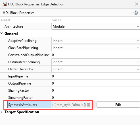
hdlset_param('EdgeDetectionAndOverlayHDL/Pixel-Stream HDL Model/Edge Detection', ...
             'SynthesisAttributes', {{'ram_style','ultra'}});
hdlset_param('EdgeDetectionAndOverlayHDL/Pixel-Stream HDL Model/Pixel Stream Aligner', ...
             'SynthesisAttributes', {{'ram_style','ultra'}});
Alternatively, you can set synthesis attributes for blocks or subsystems in the Simulink model. Right-click a block and in the HDL Coder app section, select HDL Block Properties. Click the Edit button for the SynthesisAttribute parameter and specify names and values of attributes in the table.
The table shows the resource use when you set the ram_style attribute on the Edge Detection and Pixel Stream Aligner blocks.
T =

  5×2 table

    Resource     Usage
    _________    _____

    DSP          2
    LUT          624
    Flip Flop    1329
    BRAM         0
    URAM         10
For another example of using synthesis attributes, see Use Synthesis Attributes to Map Adders to DSPs on FPGAs (HDL Coder).
See Also
Blocks
- Edge Detector | Frame To Pixels | Pixels To Frame | PSNR (Computer Vision Toolbox) | Edge Detection (Computer Vision Toolbox)
Functions
edge(Image Processing Toolbox)