Control Oscillations by Using the duration Operator
The following example focuses on the gear logic of a car as it shifts from first gear to fourth gear.
When modeling the gear changes of this system, it is important to control the oscillation
that occur. The model sf_car uses parallel state debouncer logic that
controls which gear state is active. For more information about how debouncers work in
Stateflow®, see Reduce Transient Signals by Using Debouncing Logic.
You can simplify the debouncer logic by using the duration operator. You can see this simplification in the model
sf_car_using_duration. The duration operator evaluates
a condition expression and outputs the length of time that the expression has been
true. When that length of time crosses a known time threshold, the state
transitions to a higher or lower gear.
By removing the parallel state logic and using the duration operator,
you can control oscillations with simpler Stateflow logic. The duration operator is supported only in Stateflow charts in a Simulink® model.
Control Oscillation with Parallel State Logic
Open the model sf_car.
openExample("sf_car")Select the chart shift_logic and, in the State
Chart tab, click Look Inside Mask.
The Stateflow chart shift_logic controls which gear the car is in, given
the speed of the car and how much throttle is being applied. Within
shift_logic there are two parallel states: gear_state
and selection_state. gear_state contains four
exclusive states for each gear. selection_state determines whether the
car is downshifting, upshifting, or remaining in its current gear.
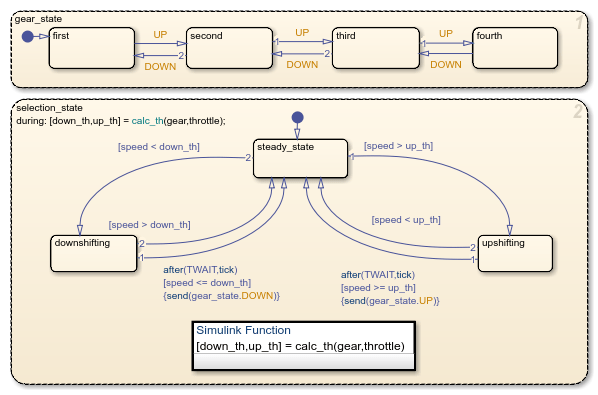
In this Stateflow chart, for the car to move from first gear to second gear, the event
UP must be sent from selection_state to
gear_state. The event is sent when the speed crosses the threshold and
remains higher than the threshold for the length of time determined by
TWAIT. When the event UP is sent,
gear_state transitions from first to
second.
Control Oscillation with the duration Operator
Open the model sf_car_using_duration.
openExample("sf_car_using_duration")Select the chart Gear_Logic and, in the State
Chart tab, click Look Inside Mask.
Within Gear_Logic there are four exclusive states for each gear. The
local variables up and down guard the transitions
between each state.

In this Stateflow chart, for the car to move from first gear to second gear, the condition
up must be true. The condition up
is defined as true if the length of time that the speed is greater than or equal to the
threshold is greater than the length of time that is specified by TWAIT.
The condition down is defined as true if the length of time that the
speed is less than or equal to the threshold is greater than the length of time that is
specified by TWAIT. The operator duration keeps track
of the length of time that the speed has been above or below the threshold.
When the up
condition is met, the active state transitions from first to
second.
By replacing the parallel state debouncer logic with the duration
operator, you can create a simpler Stateflow chart to model the gear shifting.