PMSM
Permanent magnet synchronous motor with sinusoidal flux distribution

Libraries:
Simscape /
Electrical /
Electromechanical /
Permanent Magnet
Description
The PMSM block models a permanent magnet synchronous motor (PMSM) with a three-phase wye-wound, delta-wound, or open-ended stator. Use this block to model an interior permanent magnet synchronous motor (IPMSM), surface permanent magnet synchronous motor (SPMSM), transverse flux motor, axial flux (pancake) motor, or PMSM servomotor.
PMSMs have a permanent magnet rotor and a wound stator. You can use these motors in traction applications like electric vehicles (EVs) and in actuation systems. In actuation systems, PMSMs are also called brushless servomotors. A PMSM typically has a sinusoidal back EMF profile to reduce undesirable high-frequency mechanical and electrical current harmonics compared to brushless direct current (BLDC) motors, which have a trapezoidal back EMF profile.
The PMSM block models the motor with fixed d-axis and q-axis inductances, Ld and Lq. You can use this block to model the two main types of PMSM:
SPMSM or surface permanent magnet (SPM) motor — The rotor magnets are surface mounted. Ld and Lq are equal.
IPMSM or interior permanent magnet (IPM) motor — The rotor magnets are interior to the rotor. Ld and Lq are not equal.
You can also categorize PMSMs based on the main flux paths. The main flux paths are commonly radial but can be axial, which causes much higher torques for the same physical size of motor. You can use the PMSM block to model both radial- and axial-flux PMSMs.
You can use the Winding type parameter to specify the configuration for the windings. This figure shows the equivalent electrical circuit for a wye-wound stator.

You can also model a delta-wound or open-end stator by setting Winding
type to Delta-wound or
Open-end, respectively.
You can choose different built-in parameterizations for this block. For more information, see the Predefined Parameterization section.
Note
Simscape™ Electrical™ includes several blocks that can model the same type of motor or actuator. Choose a block that has sufficient modeling detail for the engineering design questions that you need to answer. Do not use a block that has more modeling detail than you need, because higher-fidelity models slow down simulation and are more complex to parameterize.
Blocks like the PMSM block model motors with fixed or parameter-dependent coefficients with a simple equivalent circuit. These models have an intermediate level of fidelity. Use this block to design controls or systems in actuation applications, such as robotics and mechatronics, and for efficiency predictions when saturation and harmonics only weakly impact losses. For more information about choosing the right block to model your motor at the right level of fidelity, see Choose Blocks to Model Motors or Actuators.
Motor Construction
This figure shows the motor construction with a single pole-pair on the rotor.
Permanent magnets generate a rotor magnetic field that creates a sinusoidal rate of change of flux based on the rotor angle.
For the axes convention, when you set the Rotor angle
definition parameter to Angle between the a-phase
magnetic axis and the d-axis, the a-phase and
permanent magnet fluxes align when the rotor mechanical angle,
θr, is zero. When you set the
Rotor angle definition parameter to Angle
between the a-phase magnetic axis and the q-axis, the rotor
mechanical angle is the angle between the a-phase magnetic axis
and the rotor q-axis.
Equations
Voltages across the stator windings are
where:
va, vb, and vc are the individual phase voltages across the stator windings.
Rs is the equivalent resistance of each stator winding.
ia, ib, and ic are the currents flowing in the stator windings.
, , and are the rates of change for the magnetic flux in each stator winding.
The permanent magnet and the three windings contribute to the total flux linking each winding. The total flux is
where:
ψa, ψb, and ψc are the total fluxes linking each stator winding.
Laa, Lbb, and Lcc are the self-inductances of the stator windings.
Lab, Lac, Lba, and so on, are the mutual inductances of the stator windings.
ψam, ψbm, and ψcm are the permanent magnet fluxes linking the stator windings.
The inductances in the stator windings are functions of the rotor electrical angle and defined by
where:
θr is the rotor mechanical angle.
θe is the rotor electrical angle.
rotor offset is
0if you define the rotor electrical angle with respect to the d-axis, or-pi/2if you define the rotor electrical angle with respect to the q-axis.Ls is the stator self-inductance per phase. This value is the average self-inductance of each of the stator windings.
Lm is the stator inductance fluctuation. This value is the amount the self-inductance and mutual inductance fluctuate with the changing of the rotor angle.
Ms is the stator mutual inductance. This value is the average mutual inductance between the stator windings.
The permanent magnet flux linking winding a is a maximum when θe = 0° and zero when θe = 90°. Therefore, the linked motor flux is defined by:
where ψm is the permanent magnet flux linkage.
Simplified Electrical Equations
Applying Park’s transformation to the block electrical equations produces an expression for torque that is independent of the rotor angle.
Park’s transformation is defined by:
where θe is the electrical angle defined as Nθr. N is the number of pole pairs.
Using Park's transformation on the stator winding voltages and currents transforms them to the dq0 frame, which is independent of the rotor angle:
Applying Park’s transformation to the first two electrical equations produces these equations that define the block behavior:
where:
Ld = Ls + Ms + 3/2 Lm. Ld is the stator d-axis inductance.
Lq = Ls + Ms − 3/2 Lm. Lq is the stator q-axis inductance.
L0 = Ls – 2Ms. L0 is the stator zero-sequence inductance.
ω is the rotor mechanical rotational speed.
N is the number of rotor permanent magnet pole pairs.
T is the rotor torque. Torque flows from the motor case (block physical port C) to the motor rotor (block physical port R).
The PMSM block uses the original, non-orthogonal implementation of the Park transform. If you try to apply the alternative implementation, you get different results for the dq0 voltage and currents.
Alternative Flux Linkage Parameterization
You can parameterize the motor using the back EMF or torque constants which are more commonly given on motor datasheets by using the Permanent magnet flux linkage parameter.
The back EMF constant is the peak voltage induced by the permanent magnet in the per-unit rotational speed of each of the phases. The relationship between the peak permanent magnet flux linkage and the back EMF is:
The back EMF, eph, for one phase is:
The torque constant is the peak torque induced by the per-unit current of each of the phases. It is numerically identical in value to the back EMF constant when both are expressed in SI units:
When Ld=Lq and the currents in all three phases are balanced, the combined torque T is:
where Ipk is the peak current in any of the three windings.
The factor 3/2 follows from this being the steady-state sum of the torques from all phases. Therefore, the torque constant kt can also be:
where T is the measured total torque when testing with a balanced three-phase current with peak line voltage Ipk. The RMS line current is:
Calculating Iron Losses
Iron losses are divided into two terms, one representing the main magnetizing path, and the other representing the cross-tooth tip path that becomes active during field weakened operation. The iron losses model is based on [3].
The term representing the main magnetizing path depends on the induced RMS line-to-neutral stator voltage, :
This is the dominant term during no-load operation. k is the back EMF constant relating RMS volts per Hz. It is defined as , where f is the electrical frequency. The first term on the right-hand side is the magnetic hysteresis loss, the second is the eddy current loss and the third is the excess loss. The three coefficients appearing on the numerators are derived from the values that you provide for the open-circuit hysteresis, eddy, and excess losses.
The term representing the cross-tooth tip path becomes important when a demagnetizing field is set up and can be determined from a finite element analysis short-circuit test. It depends on the RMS EMF associated with the cross-tooth tip flux, :
The three numerator terms are derived from the values you provide for the short-circuit hysteresis, eddy, and excess losses.
Predefined Parameterization
There are multiple available built-in parameterizations for the PMSM block.
This pre-parameterization data allows you to set up the block to represent components by specific suppliers. The parameterizations of these permanent magnet synchronous motors match the manufacturer data sheets. To load a predefined parameterization, double-click the PMSM block, click the <click to select> hyperlink of the Selected part parameter and, in the Block Parameterization Manager window, select the part you want to use from the list of available components.
Note
The predefined parameterizations of Simscape components use available data sources for the parameter values. Engineering judgment and simplifying assumptions are used to fill in for missing data. As a result, expect deviations between simulated and actual physical behavior. To ensure accuracy, validate the simulated behavior against experimental data and refine component models as necessary.
For more information about pre-parameterization and for a list of the available components, see Simscape Electrical Part Collection.
Model Thermal Effects
You can expose thermal ports to model the effects of losses that convert power to heat. To expose the thermal ports, set the Modeling option parameter to either:
No thermal port— The block contains expanded electrical conserving ports associated with the stator windings, but does not contain thermal ports.Show thermal port— The block contains expanded electrical conserving ports associated with the stator windings and thermal conserving ports for each of the windings and for the rotor.
For more information about using thermal ports in actuator blocks, see Simulating Thermal Effects in Rotational and Translational Actuators.
Generate Derived Data Sheet
Since R2026a
You can generate a derived data sheet for the PMSM block that contains summary tables and characteristic plots similar to those that device manufacturers provide in their data sheets. A built-in MATLAB® script calculates the block-level characteristics based on the parameter values in your model. Use derived data sheets to explore the impact of your parameter choices on device characteristics, help you select manufactured parts, or share your component-level design with other members of your organization.
The derived data sheet for the PMSM block includes plots of:
Torque and current versus rotor speed at peak torque and the maximum AC voltage.
Torque, efficiency, shaft power, and stator current versus speed at 50% and 100% of the rated stator current.
If you set the Winding type parameter to
Open-end, the calculations assume that one end
connects to the ground.
To generate a derived data sheet:
Open the MATLAB script by clicking the Open live script button next to the Derived data sheet parameter in the Utilities section of the block dialog box.
In the script that opens, specify values for:
Peak line current
Peak maximum allowable line current
Maximum stator line-to-line peak voltage
Rated rotor speed
Maximum rotor speed
Click the Generate Data Sheet button in the script.
For more information about derived data sheets, see Generate Derived Data Sheets.
Variables
To set the priority and initial target values for the block variables before simulation, use the Initial Targets section in the block dialog box or Property Inspector. For more information, see Set Priority and Initial Target for Block Variables.
Nominal values provide a way to specify the expected magnitude of a variable in a model. Using system scaling based on nominal values increases the simulation robustness. You can specify nominal values using different sources, including the Nominal Values section in the block dialog box or Property Inspector. For more information, see System Scaling by Nominal Values.
Examples
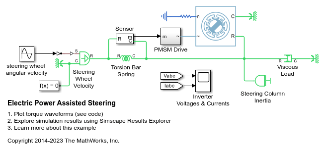
Electric Power Assisted Steering
Use a Permanent Magnet Synchronous Motor (PMSM) to amplify driver-applied force in a power-assisted automobile steering system.

Model Faulted PMSM
Model a faulted permanent magnet synchronous motor (PMSM) using Simscape™ Electrical™. Normally when modeling a PMSM, you can represent each winding as a single entity with associated inductance, induced back electromotive force (EMF), and mutual inductive coupling to adjacent windings. However, when a winding fault occurs, the single entity assumption breaks down. To correctly capture the resulting dynamics, you must model the motor at a winding slot level. This requires modeling in the magnetic domain.

Model a Three-Phase PMSM Drive
A permanent magnet synchronous machine (PMSM) in wye-wound and delta-wound configuration and an inverter sized for use in a typical hybrid vehicle. The inverter connects directly to the vehicle battery, but you can also implement a DC-DC converter stage in between. Use this model to design the PMSM controller by selecting the architecture and gains to achieve the desired performance. To check the turn-on and turn-off timing of the IGBT, replace the IGBT devices with the more detailed N-Channel IGBT block. For complete vehicle modeling, use the Motor & Drive (System Level) block to abstract the PMSM, inverter, and controller with an energy-based model.

Three-Phase PMSM Drive with Thermal Model
A Permanent Magnet Synchronous Machine (PMSM) and an inverter sized for use in a typical hybrid vehicle. The PMSM includes a thermal model and empirical iron losses. The inverter is connected directly to the vehicle battery, but you can also implement a DC-DC converter stage in between. You can use this model to design the PMSM controller, by selecting the architecture and the gains to achieve the desired performance. The initial temperature of the stator windings and rotor is set to 25 degrees Celsius. Ambient temperature is 27 degrees Celsius. The Scopes subsystem contains scopes that allow you to see the simulation results.

Parameterize a Permanent Magnet Synchronous Motor
Estimate the back EMF and torque constants of a blackbox permanent magnet synchronous motor (PMSM) with an unknown flux linkage. You can use either the back EMF or torque constant to describe the flux linkage and parameterize a Simscape™ Electrical™ PMSM block. This parameterization allows you to accurately replicate the blackbox motor's behavior in simulation.

IPMSM Torque Control
Control the torque in an interior permanent magnet synchronous machine (IPMSM) based automotive electrical-traction drive. A high-voltage battery feeds the IPMSM through a controlled three-phase converter. The IPMSM operates in both motoring and generating modes according to the load. An ideal angular velocity source provides the load. The Control subsystem uses an open-loop approach to control the IPMSM torque and a closed-loop approach to control the current. At each sample instant, the torque request is converted to relevant current references. The current control is PI-based and uses a sample rate that is faster than the rate that is used for torque control. The simulation uses several torque steps in both motor and generator modes. The task scheduling is designed in Stateflow®. The Scopes subsystem contains scopes that allow you to see the simulation results.

IPMSM Torque-Based Load Control
Control the torque in an interior permanent magnet synchronous motor (IPMSM) based drive. A high-voltage battery feeds the IPMSM through a controlled three-phase inverter. A ramp of torque request is provided to the motor controller. The load torque is quadratically dependent on the rotor speed. The Control subsystem uses an open-loop approach to control the IPMSM torque and a closed-loop approach to control the current. At each sample instant, the torque request is converted to relevant current references. The current control is PI-based and uses a sample rate that is faster than the rate that is used for torque control. The task scheduling is designed in Stateflow®. The Scopes subsystem contains scopes that allow you to see the simulation results.

IPMSM Velocity Control
Control the rotor angular velocity in an interior permanent magnet synchronous machine (IPMSM) based automotive electrical-traction drive. A high-voltage battery feeds the IPMSM through a controlled three-phase converter. The IPMSM operates in both motoring and generating modes according to the load. An ideal torque source provides the load. The Scopes subsystem contains scopes that allow you to see the simulation results. The Control subsystem includes a multi-rate PI-based cascade control structure which has an outer angular-velocity-control loop and two inner current-control loops. The task scheduling in the Control subsystem is implemented as a Stateflow® state machine. During the one-second simulation, the angular velocity demand is 0 rpm, 500 rpm, 2000 rpm, and then 3000 rpm.
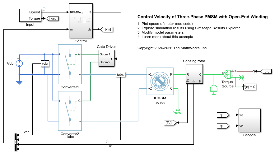
Control Velocity of Three-Phase PMSM with Open-End Winding
Control the rotor angular velocity in an interior permanent magnet synchronous machine (IPMSM) with an open-end winding. A high-voltage battery feeds the IPMSM through two controlled three-phase converters. The IPMSM operates in both motoring and generating modes according to the load. An ideal torque source provides the load. The Scopes subsystem contains scopes that allow you to see the simulation results. The Control subsystem includes a PI-based field oriented control structure. During the one-second simulation, the angular velocity demand is 0 rpm, 500 rpm, 2000 rpm, and then 3000 rpm.
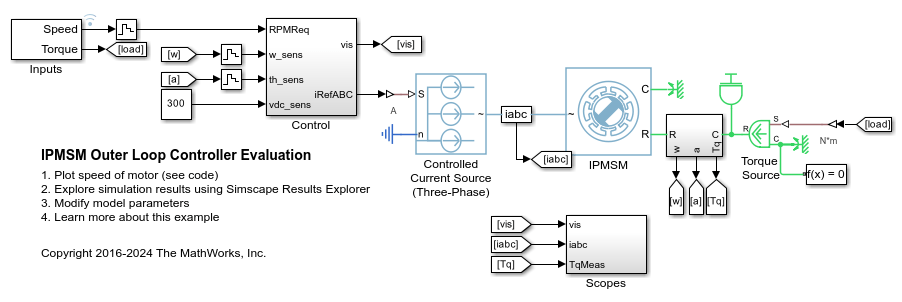
IPMSM Outer Loop Controller Evaluation
Control the rotor angular velocity in an interior permanent magnet synchronous machine (IPMSM) based electrical-traction drive. For evaluation of the outer loop velocity controller, the inner loop current controller is replaced by a three-phase controlled current source. An ideal torque source provides the load. The Scopes subsystem contains scopes that allow you to see the simulation results. The Control subsystem includes a PI-based outer loop controller. During the three-seconds simulation, the angular velocity demand is -1000, 2000, 3000, 4000, and then 5000 rpm.
Ports
Conserving
Parameters
References
[1] Kundur, P. Power System Stability and Control. New York, NY: McGraw Hill, 1993.
[2] Anderson, P. M. Analysis of Faulted Power Systems. Hoboken, NJ: Wiley-IEEE Press, 1995.
[3] Mellor, P.H., R. Wrobel, and D. Holliday. A computationally efficient iron loss model for brushless AC machines that caters for rated flux and field weakened operation. IEEE Electric Machines and Drives Conference. May 2009.
Extended Capabilities
Version History
Introduced in R2013bSee Also
Simscape Blocks
- BLDC | FEM-Parameterized PMSM | FEM-Parameterized Synchronous Machine | Hybrid Excitation PMSM | Magnetic Rotor | Motor & Drive (System Level) | PMSM (DQ0) | Rotating Air Gap