Hybrid Excitation PMSM
Hybrid excitation synchronous machine with three-phase wye-wound stator
Libraries:
Simscape /
Electrical /
Electromechanical /
Permanent Magnet
Description
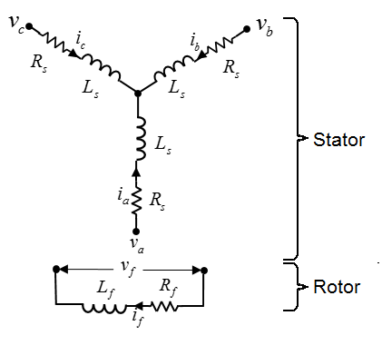
The Hybrid Excitation PMSM block represents a hybrid excitation synchronous machine with a three-phase wye-wound stator. Permanent magnets and excitation windings provide the machine excitation. Use this block to model hybrid excitation permanent magnet synchronous motors (PMSMs), doubly-excited PMSMs, and synchronous motors. This figure shows the equivalent electrical circuit for the stator and rotor windings.

You can also model the permanent magnet synchronous motor either in a delta-wound or
in an open-end configuration by setting Winding type to
Delta-wound or Open-end,
respectively.
Motor Construction
The diagram shows the motor construction with a single pole-pair on the rotor. For the axes convention, when rotor mechanical angle θr is zero, the a-phase and permanent magnet fluxes are aligned. The block supports a second rotor axis definition for which rotor mechanical angle is defined as the angle between the a-phase magnetic axis and the rotor q-axis.
Equations
Voltages across the stator windings are defined by
where:
va, vb, and vc are the individual phase voltages across the stator windings.
Rs is the equivalent resistance of each stator winding.
ia, ib, and ic are the currents flowing in the stator windings.
and are the rates of change of magnetic flux in each stator winding.
The voltage across the field winding is expressed as
where:
vf is the individual phase voltage across the field winding.
Rf is the equivalent resistance of the field winding.
if is the current flowing in the field winding.
is the rate of change of magnetic flux in the field winding.
The permanent magnet, excitation winding, and the three star-wound stator windings contribute to the flux linking each winding. The total flux is defined by
where:
ψa, ψb, and ψc are the total fluxes linking each stator winding.
Laa, Lbb, and Lcc are the self-inductances of the stator windings.
Lab, Lac, Lba, Lbc, Lca, and Lcb are the mutual inductances of the stator windings.
ψam, ψbm, and ψcm are the magnetization fluxes linking the stator windings.
Lamf, Lbmf, and Lcmf are the mutual inductances of the field winding.
The inductances in the stator windings are functions of rotor electrical angle and are defined by
where:
N is the number of rotor pole pairs.
θr is the rotor mechanical angle.
θe is the rotor electrical angle.
rotor offset is
0if you define the rotor electrical angle with respect to the d-axis, or-pi/2if you define the rotor electrical angle with respect to the q-axis.Ls is the stator self-inductance per phase. This value is the average self-inductance of each of the stator windings.
Lm is the stator inductance fluctuation. This value is fluctuation in self-inductance and mutual inductance with changing rotor angle.
Ms is the stator mutual inductance. This value is the average mutual inductance between the stator windings.
The magnetization flux linking winding, a-a’ is a maximum when θe = 0° and zero when θe = 90°. Therefore:
and
where:
ψm is the linked motor flux.
Lmf is the mutual field armature inductance.
ψf is the flux linking the field winding.
Lf is the field winding inductance.
is the transform of the Lmf vector, that is,
Simplified Equations
Applying the Park transformation to the block electrical defining equations produces an expression for torque that is independent of rotor angle.
The Park transformation is defined by
Applying the Park transformation to the first two electrical defining equations produces equations that define the block behavior:
and
where:
vd, vq, and v0 are the d-axis, q-axis, and zero-sequence voltages. These voltages are defined by
id, iq, and i0 are the d-axis, q-axis, and zero-sequence currents, defined by
Ld is the stator d-axis inductance. Ld = Ls + Ms + 3/2 Lm.
ω is the mechanical rotational speed.
Lq is the stator q-axis inductance. Lq = Ls + Ms − 3/2 Lm.
L0 is the stator zero-sequence inductance. L0 = Ls – 2Ms.
T is the rotor torque. For the Hybrid Excitation PMSM block, torque flows from the machine case (block conserving port C) to the machine rotor (block conserving port R).
J is the rotor inertia.
TL is the load torque.
Bm is the rotor damping.
Model Thermal Effects
You can expose thermal ports to model the effects of generated heat and motor temperature. To expose the thermal ports, set the Modeling option parameter to either:
No thermal port— The block contains expanded electrical conserving ports associated with the stator windings, but does not contain thermal ports.Show thermal port— The block contains expanded electrical conserving ports associated with the stator windings and thermal conserving ports for each of the windings and for the rotor.
For more information about using thermal ports in actuator blocks, see Simulating Thermal Effects in Rotational and Translational Actuators.
Variables
To set the priority and initial target values for the block variables before simulation, use the Initial Targets section in the block dialog box or Property Inspector. For more information, see Set Priority and Initial Target for Block Variables.
Nominal values provide a way to specify the expected magnitude of a variable in a model. Using system scaling based on nominal values increases the simulation robustness. You can specify nominal values using different sources, including the Nominal Values section in the block dialog box or Property Inspector. For more information, see System Scaling by Nominal Values.
Examples
Assumptions
Flux distribution is sinusoidal.
Ports
Conserving
Parameters
References
[1] Kundur, P. Power System Stability and Control. New York, NY: McGraw Hill, 1993.
[2] Anderson, P. M. Analysis of Faulted Power Systems. Hoboken, NJ: Wiley-IEEE Press, 1995.
[3] Mbayed, R. Contribution to the Control of the Hybrid Excitation Synchronous Machine for Embedded Applications. Universite de Cergy Pontoise, 2012.
[4] Luo, X. and T. A. Lipo. “A Synchronous/Permanent Magnet Hybrid AC Machine.” IEEE Transactions of Energy Conversion. Vol. 15, No 2 (2000), pp. 203–210.


