Magnetic Rotor

Libraries:
Simscape /
Electrical /
Electromechanical
Description
The Magnetic Rotor block represents the magnetic and mechanical characteristics of a rotor component in a permanent magnet synchronous machine (PMSM). In particular, this block models the air gaps between the stator teeth and a rotating permanent magnet rotor as an array of Rotating Air Gap blocks.
The Number of stator teeth parameter specifies the number of
Rotating Air Gap blocks that comprise the
Magnetic Rotor block. This figure shows the
equivalent circuit of the block when you set the Number of stator
teeth parameter to 9:

If the rotor angle is zero, one of the rotor magnets perfectly aligns with the middle of the first stator tooth. The orientation of this permanent magnet opposes the flux flow from port N to port S.
The magnetic port N is an array of magnetic ports with a length equal to the value of the Number of stator teeth parameter. To connect the individual magnetic ports corresponding to each stator tooth, you need a Magnetic Demux block. You can write your own Magnetic Demux block using Simscape code, or use the block from the Model Faulted PMSM example model.
This figure shows the relationship between the parameters of the Magnetic Rotor block and their physical values inside a permanent magnet motor.
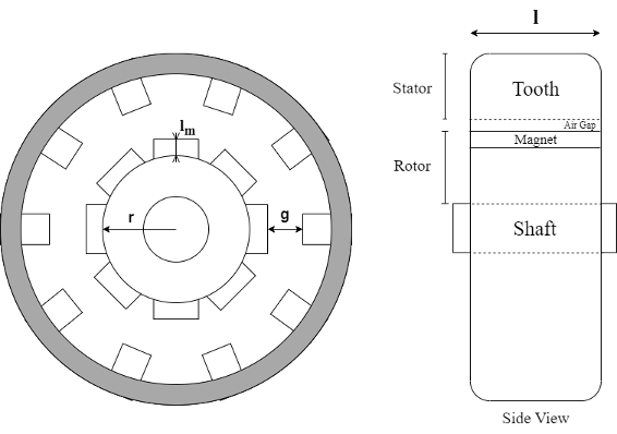
r is the value of the Rotor radius parameter.
g is the value of the Air gap parameter.
lm is the value of the Permanent magnet length (in direction of flux) parameter.
l is the value of the Tooth depth (in direction of shaft) parameter.
The rotor circumference is equal to . Then, the width of a permanent magnet on the rotor is equal to , where N is the Number of rotor pole pairs.
Faults
To model a fault in the Magnetic Rotor block, in the Faults section, click Add fault next to the fault that you want to model. For more information about fault modeling, see Fault Behavior Modeling and Fault Triggering.
The Magnetic Rotor block supports faulting the rotor poles. This faulted behavior corresponds to one or more magnets (poles) in the rotor having a weakened magnetic field. You can apply a reduction factor to the flux density of any of the rotor poles by specifying the Flux multipliers for faulted rotor poles parameter.
The transition to the faulted values linearly interpolates over the time period that you specify in the Duration of transition to faulted parameter. Use this parameter to emulate how an overheated permanent magnet gradually loses its magnetization over time.
Examples

Model Faulted PMSM
Model a faulted permanent magnet synchronous motor (PMSM) using Simscape™ Electrical™. Normally when modeling a PMSM, you can represent each winding as a single entity with associated inductance, induced back electromotive force (EMF), and mutual inductive coupling to adjacent windings. However, when a winding fault occurs, the single entity assumption breaks down. To correctly capture the resulting dynamics, you must model the motor at a winding slot level. This requires modeling in the magnetic domain.
Assumptions and Limitations
The Magnetic Rotor block assumes that the rotor magnets are surface-mounted and that the associated induced voltage is sinusoidal.
Ports
Conserving
Parameters
Extended Capabilities
Version History
Introduced in R2023b