Deploy and Verify Modulation Classification on RFSoC Devices
This example shows how to deploy a pretrained convolutional neural network (CNN) for modulation classification to the AMD® Zynq® UltraScale+™ RFSoC devices. The pretrained network is trained by using generated synthetic and channel-impaired waveforms.
Introduction
The modulation classification application consists of two main modules: a preprocessing module and a neural network module. The preprocessing module formats the input signal from the RF Data Converter block and feeds the data to the NN block for classification. The neural network module consists of multiple fully connected layers and convolutional layers. These layers perform feature extraction and effective modulation classification of the modulated input signals. This example is based on the Modulation Classification by Using FPGA (Deep Learning HDL Toolbox) example in MATLAB®.
Supported Hardware Platforms
AMD Zynq UltraScale+ RFSoC ZCU111 Evaluation Kit + XM500 balun card
Configure Deep Learning Processor and Generate IP Core
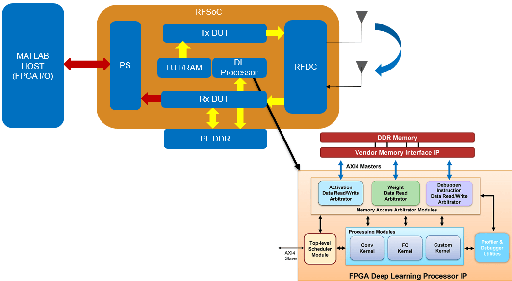
The deep learning processor IP core accesses the preprocessed input from the DDR memory, performs the classification, and loads the output back into the memory. To generate the deep learning processor IP core with the required interfaces, create a deep learning processor configuration by using the dlhdl.ProcessorConfig (Deep Learning HDL Toolbox) class. In the processor configuration, set the InputRunTimeControl and OutputRunTimeControl properties to register mode. These properties indicate the interface type between the input and output of the deep learning processor. To learn about these properties, see Interface with the Deep Learning Processor IP Core (Deep Learning HDL Toolbox). Specify the TargetPlatform property of the processor configuration object as Generic Deep Learning Processor. It takes some time to generate the deep learning processor IP core. Use the following configuration to build the deep learning processor IP for modulation classification. Use the dlhdl.buildProcessor function with the hPC object to generate the deep learning IP core.
hPC = dlhdl.ProcessorConfig;
hPC.InputRunTimeControl = "register";
hPC.OutputRunTimeControl = "register";
hPC.TargetPlatform = 'Generic Deep Learning Processor';
hPC.setModuleProperty('conv','LRNBlockGeneration','on');
hPC.setModuleProperty('conv','SegmentationBlockGeneration','off');
hPC.setModuleProperty('conv','ConvThreadNumber',9);
dlhdl.buildProcessor(hPC);
The generated IP core contains a standard set of registers. An IP core report is generated in the same folder as the IP core, with the name testbench_ip_core_report.html.
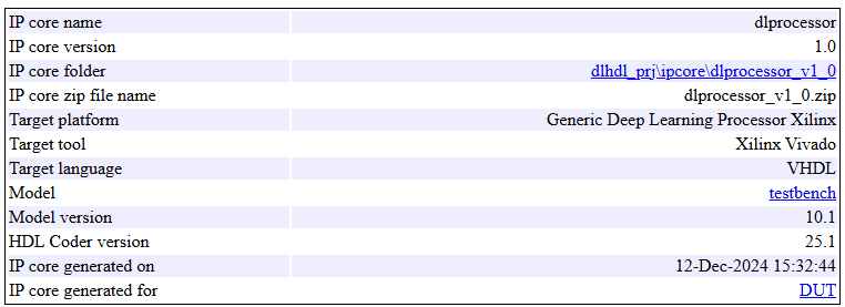
You require IP core name and IP core folder in the subsequent step, Set Target Reference Design, of the DUT IP core generation workflow. The IP core report contains the address map of the registers that are needed for handshaking with the input and output of the deep learning processor IP core.
Model Device Under Test
This section describes the design of the modulation classification system. The design is based on the Deep Learning design with I/Q DAC/ADC and real-time interfaces reference design in SoC Blockset™. The reference design supports the AXI4-Stream to hardware, hardware to AXI4-Stream, AXI4 Master DDR, RF data converter, and deep learning HDL interfaces. The reference design also supports up to 128-bit wide AXI4-Stream and AXI4 Master interfaces to operate at higher sampling rates of the RF data converter. To learn more about the reference design, see Reference Designs for RFSoC Devices.
The reference design contains a Transmit Repeat DUT and a Capture DUT. In the Transmit Repeat DUT, there is a provision to transmit a test tone or a waveform loaded onto LUT-based RAMs. There are multiple RAMs to accommodate multiple test waveforms of interest. There is also a provision to select the Tx source either from the LUT-based RAMs or the tone generated by the NCO.
In the Capture DUT, there is a provision for triggering and capturing a frame of samples from MATLAB. This is achieved through ADI AXI DMA controller, which is used to move the data from the FPGA fabric to the processor in the reference design. The data is sent from the trigger capture subsystem, through the DMA controller and AXI4-Stream interface, to the MATLAB host. This setup is used for capturing real-world samples for offline training.
The DUT contains two AXI4 Master interfaces. One AXI4 interface is connected to the deep learning processor IP core, and the other is connected to the DDR memory interface generator (MIG) IP.
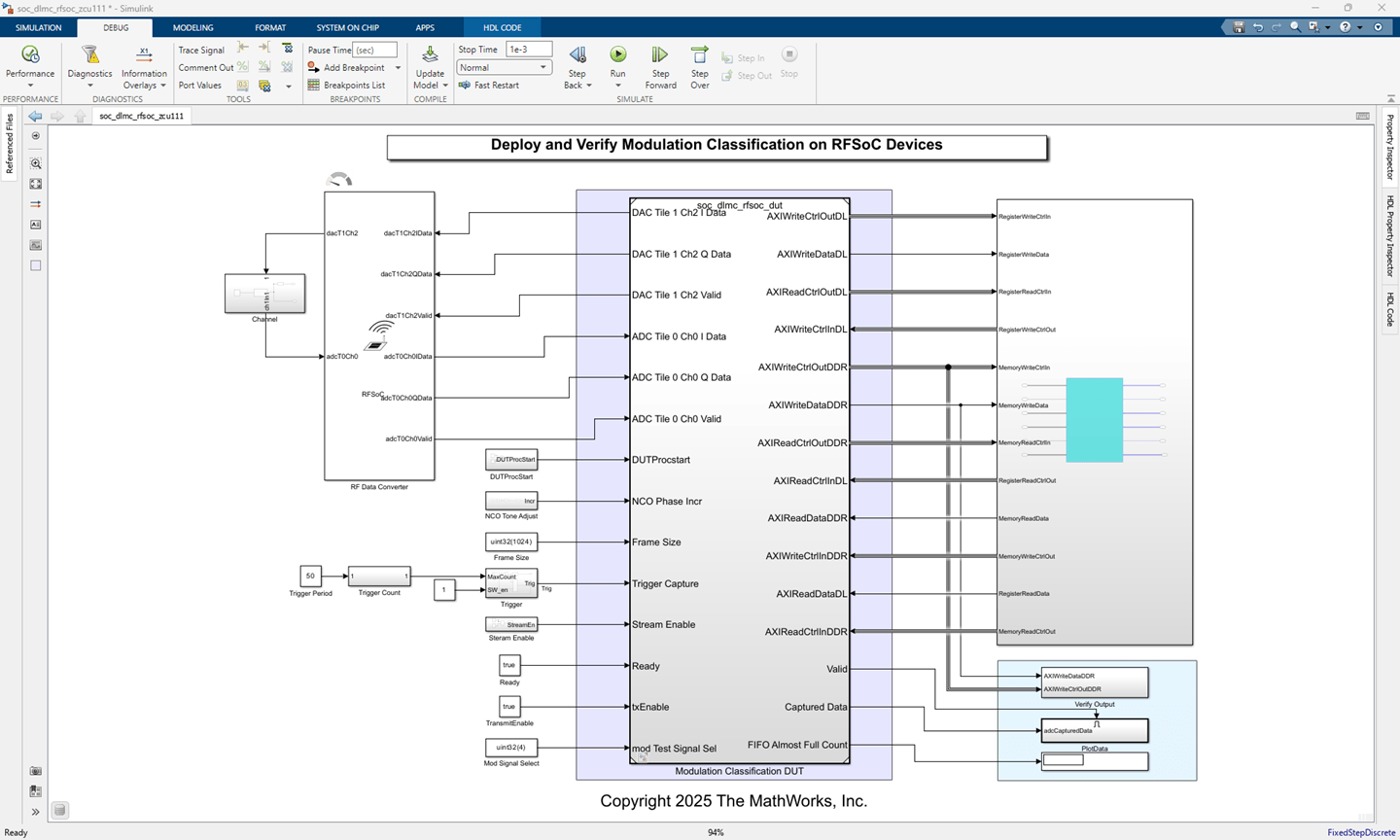
Start the targeting workflow by opening the soc_dlmc_rfsoc_zcu111.slx model. Right-click the Modulation Classification DUT. To add the HDL Coder app options to the menu, point to Select Apps and click the HDL Coder button. Then, in the HDL Coder app section, select HDL Workflow Advisor.
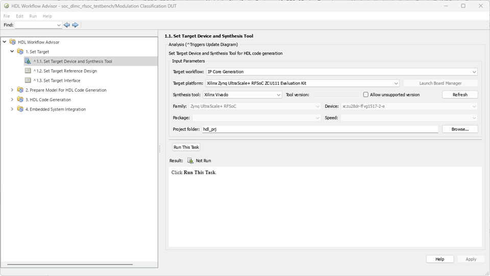
1. In step 1.1, set Target workflow to IP Core Generation and Target platform to Xilinx Zynq UltraScale+ RFSoC ZCU111 Evaluation Kit.
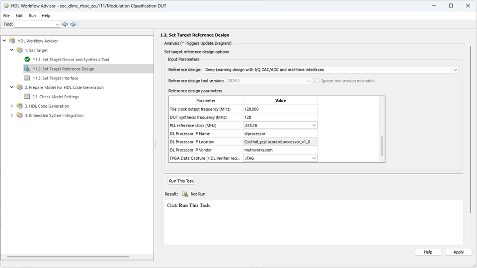
2. In step 1.2, set Reference design to Deep Learning design with I/Q DAC/ADC and real-time interfaces. Under Reference design parameters, update the DL Processor IP location parameter value with the path of the generated deep learning HDL IP core. You can obtain this path from the IP core report. Update DL Processor IP vendor to mathworks.com.
3. In step 1.3, map the target platform interfaces to the input and output ports of the DUT.
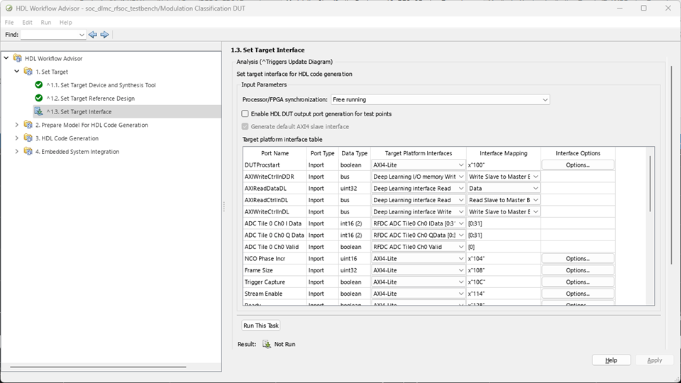
AXI4-Stream to Software Master Interface — The Captured Data and Valid ports of the DUT are mapped to the Data and Valid ports of the AXI4-Stream to Software Master interface, respectively.
AXI4-Lite Interface — The DUTProcstart register is mapped to the AXI4-Lite register. When this register is written, it triggers the input handshaking process. Choosing the AXI4-Lite interface directs HDL Coder™ to generate a memory-mapped register in the FPGA fabric. You can access this register from software by running on the ARM® processor. Other ports, such as Trigger Capture, Stream Enable, txEnable, Ready, and Frame Size, are also mapped to AXI4-Lite.
AXI4 Master DL I/O Interface — The AXIWriteCtrlInDDR, AXIReadCtrlInDDR, AXIReadDataDDR, AXIWriteCtrlOutDDR, AXIWriteDataDDR, and AXIReadCtrlOutDDR ports of the DUT are mapped to the AXI4 Master DDR interface. The read channel of the AXI4 Master DDR interface is mapped to the Deep Learning I/O memory read interface, and the write channel of the AXI4 Master DDR interface is mapped to the Deep Learning I/O memory write interface. This interface is used for data transfer between the Preprocess DUT and the PL DDR. Using the write channel of this interface, the preprocessed data is written to the PL DDR, which can then be accessed by the deep learning processor IP.
AXI4 Master DL Interface — The AXIReadDataDL, AXIReadCtrlInDL, AXIWriteCtrlInDL, AXIReadCtrlOutDL, AXIWriteDataDL, and AXIWriteCtrlOutDL ports of the DUT are mapped to the AXI4 Master deep learning interface. The read channel of the AXI4 Master deep learning interface is mapped to the Deep Learning interface Read, and the write channel of the AXI4 Master deep learning interface is mapped to the Deep Learning interface write. This interface is used for communication between the Modulation Classification DUT and the deep learning processor IP. In this example, this interface is used for implementing input handshaking logic with the deep learning processor IP.
4. Run step 2 to prepare the design for HDL code generation.
5. Run step 3 to generate HDL code for the IP core.
6. Run step 4.1 to integrate the newly generated IP core into the reference design.
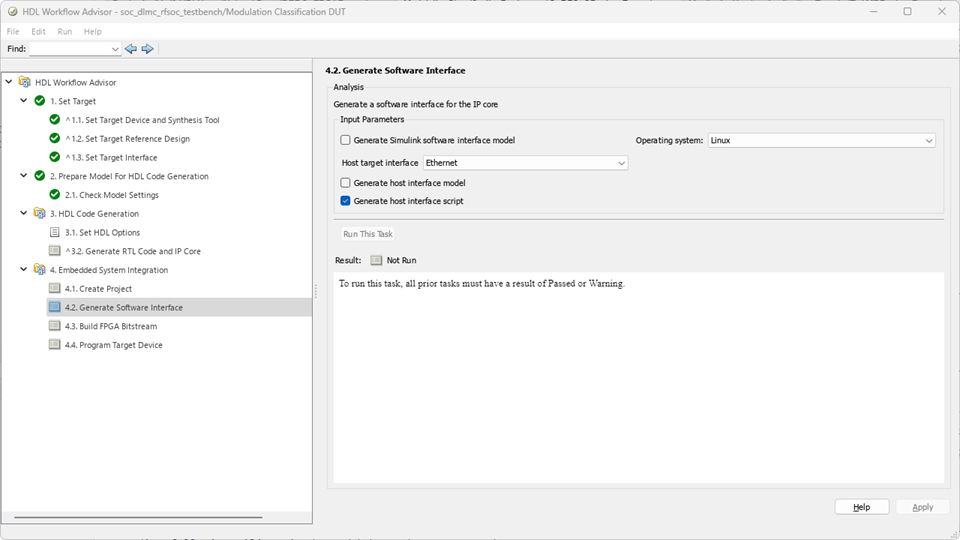
7. In step 4.2, the host interface script is created. Clear the Generate Simulink software interface model check box, as this example does not require software interface models. The host interface script, soc_dlmc_rfsoc_interface, which is generated in this step is parameterized and provided as the setupPreprocessIPInterfaces function as part of this example.
8. Run step 4.3 to generate the bitstream. The bit file is named system_wrapper.bit and is located at hdl_prj\vivado_ip_prj\vivado_prj.runs\impl_1.
Program FPGA and Configure RF Data Converter
Create the xilinxsoc object.
hProcessor = xilinxsoc();
Copy the device tree file to the /mnt folder and program the device.
system(hProcessor,'cp /mnt/refDesigns/devicetree_dl_axim_hwsw_128_swhw_128.dtb /mnt');
programFPGA(hProcessor,"hdl_prj\vivado_ip_prj\vivado_prj.runs\impl_1\system_wrapper.bit","devicetree_dl_axim_hwsw_128_swhw_128.dtb");
Configure the RF Data Converter with a pregenerated RF Data Converter System object script.
soc_dlmc_rfsoc_zcu111_rfdc_setup;
Create an FPGA object. Set up and configure the hFPGA object with the same interfaces as the generated IP core.
hFPGA = fpga(hProcessor);
gs_soc_dlmc_rfsoc_zcu111_setup(hFPGA);
Compile and Deploy Modulation Classification Network
Run the following commands to compile and deploy the deep learning modulation classification network. Create a target object to connect your target device to the host computer. Use the installed AMD Vivado® Design Suite over an Ethernet connection to program the device.
1. Update the bitstream build information in the MAT file generated during the IP core generation. The name of the MAT file is dlprocessor and it is located in pwd\dlhdl_prj\, where pwd is your present working folder. Copy the file to the present working folder. This MAT file, generated using the target platform Generic Deep Learning Processor, does not contain the board and vendor information. To update the board and vendor information, use the socUpdateBitstreamBuildInfo helper function and generate a new MAT file with the same name as the generated bitstream.
socUpdateBitstreamBuildInfo('system_wrapper.bit')
2. Create a target object to connect your target device to the host computer.
hTarget = dlhdl.Target('Xilinx','Interface','Ethernet','IpAddr','192.168.1.101');
3. Load the pretrained modulation classification network.
modulationClassification = load('dlhdltrainedModulationClassificationNetwork.mat');
net = modulationClassification.trainedNet;
4. Create a deep learning HDL workflow object by using the dlhdl.Workflow class.
hW = dlhdl.Workflow('Network',net,'Bitstream',['system_wrapper','.bit'],'Target',hTarget);
5. Compile the network, net, by using the dlhdl.Workflow object.
compile(hW);
6. Run the deploy function to deploy the network.
deploy(hW,'ProgramBitStream',false);
Verify Deployed Modulation Classification Application Using MATLAB
To verify the deployed modulation classification network using MATLAB, you use a subset of waveforms generated in the Modulation Classification by Using FPGA (Deep Learning HDL Toolbox) example. The following is the list of modulated test waveform files used in the validation. Use the predict function to validate the deep learning HDL IP response against the provided test waveform. Alternatively, you can run the soc_dlmc_rfsoc_tesbench_host_run script to verify.
List of modulated test waveforms and their respective files:
16-ary quadrature amplitude modulation (16-QAM) — QAM16.mat
64-ary quadrature amplitude modulation (64-QAM) — QAM64.mat
8-ary phase shift keying (8-PSK) — 8PSK.mat
Broadcast FM (B-FM) — B-FM.mat
Binary phase shift keying (BPSK) — BPSK.mat
Continuous phase frequency shift keying (CPFSK) — CPFSK.mat
Double sideband amplitude modulation (DSB-AM) — DSB-AM.mat
Gaussian frequency shift keying (GFSK) — GFSK.mat
4-ary pulse amplitude modulation (PAM4) — PAM4.mat
Quadrature phase shift keying (QPSK) — QPSK.mat
Single sideband amplitude modulation (SSB-AM) — SSB-AM.mat
modulationTypes = categorical(["16QAM","64QAM","8PSK","B-FM", ...
"BPSK","CPFSK","DSB-AM","GFSK","PAM4","QPSK","SSB-AM"]);
load QAM16.mat;
[prediction,~] = hW.predict(testData,'ProgramBitStream',false);
[~,idx] = max (prediction,[],2);
fprintf('FPGA Prediction: %s \n',modulationTypes(idx));
load QAM64.mat;
[prediction,speed] = hW.predict(testData,'ProgramBitStream',false);
[~,idx] = max (prediction,[],2);
fprintf('FPGA Prediction: %s \n',modulationTypes(idx));
load 8PSK.mat;
[prediction,~] = hW.predict(testData,'ProgramBitStream',false);
[~,idx] = max (prediction,[],2);
fprintf('FPGA Prediction: %s \n',modulationTypes(idx));
load B-FM.mat;
[prediction,~] = hW.predict(testData,'ProgramBitStream',false);
[~,idx] = max (prediction,[],2);
fprintf('FPGA Prediction: %s \n',modulationTypes(idx));
load BPSK.mat;
[prediction,~] = hW.predict(testData,'ProgramBitStream',false);
[~,idx] = max (prediction,[],2);
fprintf('FPGA Prediction: %s \n',modulationTypes(idx));
load CPFSK.mat;
[prediction,~] = hW.predict(testData,'ProgramBitStream',false);
[~,idx] = max (prediction,[],2);
fprintf('FPGA Prediction: %s \n',modulationTypes(idx));
load DSB-AM.mat;
[prediction,~] = hW.predict(testData,'ProgramBitStream',false);
[~,idx] = max (prediction,[],2);
fprintf('FPGA Prediction: %s \n',modulationTypes(idx));
load GFSK.mat;
[prediction,~] = hW.predict(testData, 'ProgramBitStream', false);
[~,idx] = max (prediction,[],2);
fprintf(' FPGA Prediction: %s \n',modulationTypes(idx));
load PAM4.mat ;
[prediction,~] = hW.predict(testData,'ProgramBitStream',false);
[~,idx] = max (prediction,[],2);
fprintf('FPGA Prediction: %s \n',modulationTypes(idx));
load QPSK.mat;
[prediction,~] = hW.predict(testData,'ProgramBitStream',false);
[~,idx] = max (prediction,[],2);
fprintf('FPGA Prediction: %s \n',modulationTypes(idx));
load SSB-AM.mat;
[prediction,~] = hW.predict(testData,'ProgramBitStream',false);
[~,idx] = max (prediction,[],2);
fprintf('FPGA Prediction: %s \n',modulationTypes(idx));
Profile Deployed Modulation Classification Application
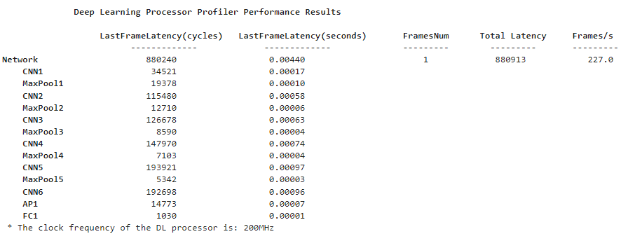
To profile the frames of data that can be processed by the deep learning IP with the deployed modulation classification network, run the following command in MATLAB. The report shows the frame latencies in different layers and the frames processed per second.
load QAM16.mat;
[prediction,~] = hW.predict(testData,'ProgramBitStream',false,Profile ='on');
Clear Objects
clear hW;
clear hTarget;
Summary
In this example, you use the Deep Learning design with I/Q DAC/ADC and real-time interfaces reference design to build a deep learning system for modulation classification. You deploy the modulation classification network, load the test waveform onto DDR, and validate the modulation classification results of the deep learning network from MATLAB.