Interface with the Deep Learning Processor IP Core
Retrieve predictions for a batch of images or for a data stream from a live camera input by using the generated deep learning processor IP core. Select between batch processing mode and streaming mode depending on available board resources, availability of input data, and application requirements. Use MATLAB® to run your deep learning network on the generated deep learning processor IP core and retrieve the network prediction from the generated deep learning processor IP core.
Create Deep Learning Processor Configuration
To generate a deep learning processor IP core that has the required interfaces for
processing multiple data frames, create a deep learning processor configuration by using the
dlhdl.ProcessorConfig class. In the deep learning processor configuration:
Set
InputRunTimeControlandOutputRunTimeControlto either port or register.You must set
InputDataInterfaceandOutputDataInterfacetoExternalMemory.
Use the dlhdl.buildProcessor function with the deep learning
processor configuration object as the input argument to generate the deep learning processor
IP core. For example, this code generates a deep learning processor IP core with the
interfaces to process multiple data frames.
hPC = dlhdl.ProcessorConfig;
hPC.InputRunTimeControl = 'port';
hPC.OutputRunTimeControl = 'port'
hPC.InputDataInterface = 'External Memory';
hPC.OutputDataInterface = 'External Memory';
dlhdl.buildProcessor(hPC);
Select Data Processing Mode
Choose between batch processing mode and streaming mode based on your resource requirements, availability of inputs, and interface complexity. This table lists the different selection criteria and which mode to select based on the selection criteria.
| Selection Criteria | Batch Processing Mode | Streaming Mode |
| Availability of input data | All input data must be available before you trigger the deep learning processor IP core to start processing data. | Stream input data as and when data is available. |
| Memory requirements | Can require large memory resources to store all the input data and processed output data as the deep learning processor IP core processes all the data together. | Requires minimal memory resources. The smallest memory required is twice the size of one input data frame. |
| Interface Complexity | Simple protocol. No handshaking protocol required. | Complex protocol. You must implement a handshaking protocol. |
Design Processing Mode Interface Signals
You can group the interface signals into run-time signals, handshaking signals, and setup control signals. Handshaking signals are used only when the data processing mode is set to streaming mode.
Run-Time Control Signals
This table lists the run-time control signals, data types, interface types, and
description. The interface type depends on the RunTimeControl settings.
For example, if RunTimeControl is set to port, the
interface type is port.
| Signal Name | Data Type | Configuration Control Parameter or | Interface Type (Port or Register) | Description | Interface Direction (Input or Output) |
InputStart | logical | RunTimeControl | port/register | Signal from the user to the deep learning processor IP core to start processing the data. | Input |
FrameCount | integer | RunTimeControl | port/register | Signal from the user to the deep learning processor IP core specifying the number of input data frames. | Input |
InputStop | logical | RunTimeControl | port/register | Signal to stop the continuous streaming mode. To stop the continuous
streaming mode, set this signal to true. | Input |
Run-Time Status Signals
This table lists the run-time control signals, data types, interface types, and
description. The interface type depends on the RunTimeStatus settings.
For example, if RunTimeStatus is set to port, the
interface type is port.
| Signal Name | Data Type | Configuration Control Parameter or | Interface Type (Port or Register) | Description | Interface Direction (Input or Output) |
Done | logical | RunTimeStatus | port/register | Signal indicating that the deep learning processor IP core has processed all input data and written the last output to memory. | Output |
StreamingDone | logical | RunTimeStatus | port/register | Signal to test streaming mode. During testing, the signal becomes true when you retrieve the last output. | Output |
Handshaking signals
This table lists the handshaking signals, data types, interface types, and
description. These signals are used for streaming mode. The interface type depends on the
InputRunTimeControl and OutputRunTimeControl
settings. For example, if InputRunTimeControl is set to
port, the interface type is port. To ensure proper
functionality of the generated deep learning processor, you must specify the values for
the signals that are ports or registers.
| Signal Name | Data Type | Configuration Control Parameter or | Interface Type (Port or Register) | Description | Interface Direction (Input or Output) |
InputAddr | uint32 | InputStreamControl | port/register | Signal indicating the address location in memory for loading the input data.
Use this signal when the InputValid signal is high. | Output |
InputNext | logical | InputStreamControl | port/register | Signal to the deep learning processor IP core to indicate that the next data
frame is available for processing. Use this signal when the
InputValid signal is high. | Input |
InputSize | uint32 | InputStreamControl | port/register | Signal indicating the size in bytes of the next input data frame. Use
this signal when the The | Output |
InputValid | logical | InputStreamControl | port/register | Signal from the deep learning processor IP core indicating that the input data is valid. | Output |
OutputAddr | uint32 | OutputStreamControl | port/register | Signal indicating the address location in memory from where to retrieve the
output data. Use this signal when the OutputValid signal is
high. | Output |
OutputNext | logical | OutputStreamControl | port/register | Signal to the deep learning processor IP core to indicate that you have read
the current output data frame. Use this signal when the
OutputValid signal is high. | Input |
OutputSize | uint32 | OutputStreamControl | port/register | Signal indicating the size of the next output data frame in bytes. Use this
signal when the OutputValid signal is high. | Output |
OutputValid | logical | OutputStreamControl | port/register | Signal from the deep learning processor IP core indicating that the output data is valid. | Output |
Setup Control Signals
This table lists the setup control signals, data types, interface types, and
description. The interface type depends on the SetupControl settings.
For example, if SetupControl is set to port, the
interface type is port.
| Signal Name | Data Type | Configuration Control Parameter | Interface Type (Port or Register) | Description | Interface Direction (Input or Output) |
|---|---|---|---|---|---|
StreamingMode | logical | SetupControl | port/register | Signal from the user to the deep learning processor IP core specifying the
data processing mode. false selects buffer mode and
true selects streaming mode. | Input |
UseCustomBaseAddr | logical | SetupControl | port/register | Signal from the user to the deep learning processor IP core to use the
customer specified input and output base addresses.true selects
user addresses and false selects compiler generated
addresses. | Input |
InputBaseAddr | uint32 | SetupControl | port/register | User provided input base address. Specify the address before you toggle the
InputStart signal. | Input |
OutputBaseAddr | uint32 | SetupControl | port/register | User provided output base address. Specify the address before you toggle the
InputStart signal. | Input |
Debug Registers
This table lists the debug registers, data types and description. To get a list of the
debug registers, see getStatusRegisterList. Use the readStatusRegister method to read information from the debug registers.
| Debug Register Name | Data type | Description |
DLStart | logical | Signal indicating that the deep learning processor has started. |
CONVLayerStartCount | uint | Signal indicating the total number of frames for all the convolution layers in the network. |
CONVLayerEndCount | uint | Signal indicating the total number of frames processed by the convolution layers in the network. |
CONVLayerActive | logical | Signal indicating that the conv layer is active and
processing data |
FCLayerStartCount | uint | Signal indicating the total number of frames for all the fully connected layers in the network. |
FCLayerEndCount | uint | Signal indicating the total number of frames processed by the fully connected layers in the network. |
FCLayerActive | logical | Signal indicating that the FC layer is active and
processing data |
FCLayerStartCount | uint | Signal indicating the total number of frames for all the custom layers in the network. |
FCLayerEndCount | uint | Signal indicating the total number of frames processed by the custom layers in the network. |
FCLayerActive | logical | Signal indicating that the custom layer is active and
processing data |
FrameStartCount | uint | Signal indicating the current frame being processed. |
FrameEndCount | uint | Signal indicating the last frame that was processed. |
DLDone | logical | Signal indicating that the deep learning processor has completed processing data. |
Design Batch Processing Mode Interface
When you have all your input data available and access to large double data rate (DDR)
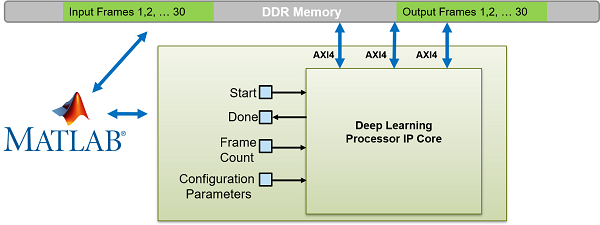
memory space, process multiple frames by using the batch processing mode. The figure shows
the generated deep learning processor IP core with interface signals for the batch
processing mode of operation. You use MATLAB and a dlhdl.Workflow object to run your deep learning network
on the deep learning processor IP core. Retrieve the network prediction results from the
deep learning processor IP core. To use batch mode, set the FrameCount
register to a value greater than or equal to one.
To process a single data frame set the FrameCount register value to
one. If the FrameCount is set to zero the deep learning processor runs
intermittently and the Done signal does not become
true.
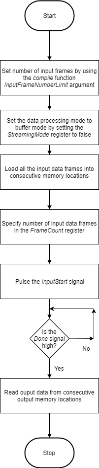
This flowchart shows the operation of the batch processing mode.
This timing diagram shows the operation of the batch processing mode.
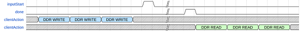
Load all the data frames into consecutive input DDR memory locations,
toggle the inputStart signal, wait for the done signal
to go high, and then read the output data from the consecutive output DDR memory locations.
The clientAction signals represent your actions of loading input data and
reading output data into the DDR memory.
Design Streaming Mode Interface
When your input data is streaming in, when you have access to limited DDR memory space, and when your application requires handshaking protocols, process multiple frames by using the streaming mode. The figure shows the generated deep learning processor IP core with interface signals for the streaming mode of operation. In this figure, the live camera streams data to an image preprocessing design under test (DUT) that implements the streaming mode handshaking protocol to interact with the generated deep learning processor IP core.
Date can be streamed to the deep learning processor IP core in two modes:
Stream Data up to a frame count value— In this mode the deep learning processor processes data frames up to the value specified in
FrameCount. After processing all the frames the deep learning processor IP core sets theDonesignal totrue. To use this mode theFrameCountmust be set to a value greater than or equal to one.To process a single data frame set the
FrameCountregister value to one.Continuous streaming mode— In this mode the deep learning processor IP core processes data frames until you set the
InputStopvalue totrue. To use this mode theFrameCountmust be set to zero.

Streaming Mode up to a Frame Count
This flowchart shows the operation of the streaming mode data processing mode. The read and write operations occur in parallel.
The value set in the InputFrameNumberLimit specifies in terms of
input and output frames the space that is allocated in the DDR for the input and output
ring buffers. In streaming mode, this value must be at least two. When backpressure is
applied, for values larger than two the deep learning processor IP core:
Continues to accept input data until the input ring buffer is full.
Continues to produce output data until the output ring buffer is full.
As streaming continues, the input and output buffers fill and drain based on output backpressure and input data availability.
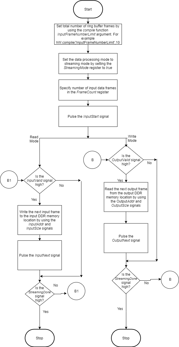
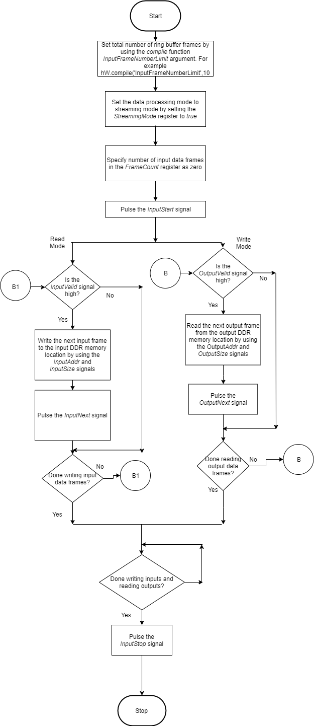
This flowchart shows the operation of the streaming mode up to a frame count. The read and write operations occur in parallel.
This timing diagram shows the operation of the streaming mode up to a frame count.
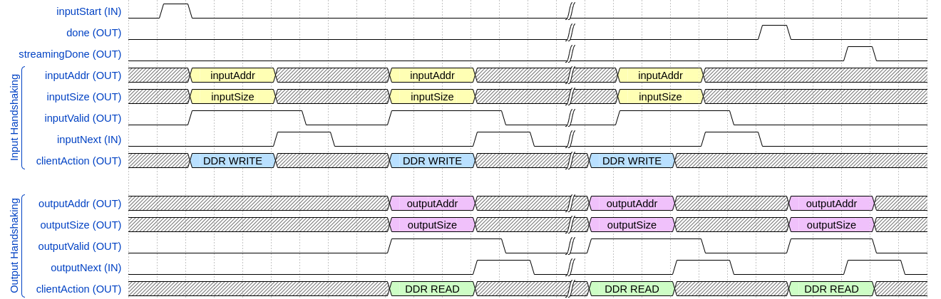
Set the
InputFrameNumberLimitargument of thecompilemethod to a value greater than two.Set the
StreamingModesignal totrue.Set the number of data frames to process in the
FrameCountregister.Pulse the
inputStartsignal. These next actions can be performed in parallel:Wait for the
inputValidsignal to becometrueand then:Use the
inputAddrandinputSizesignals to write the next input data frame to DDR memory.Pulse the
inputNextsignal.
Wait for the
outputValidsignal to becometrueand then:Use the
outputAddrandoutputSizesignals to read the processed output data frame.Pulse the
outputNextsignal.
Once the deep learning processor IP core has processed all the frames it sets the
donesignal totrue.
The clientAction signals represent your actions of
loading input data and reading output data into the DDR memory.
Continuous Streaming Mode
You can continuously stream data to the deep learning processor in continuous
streaming mode. To use the continuous streaming mode, set the
FrameCount to zero. To stop the data processing set the
InputStop signal to true. The value set in the
InputFrameNumberLimit specifies in terms of input and output frames
the space that is allocated in the DDR for the input and output ring buffers. When
backpressure is applied, for values larger than the value in
InputFrameNumberLimit the deep learning processor IP core:
Continues to accept input data until the input ring buffer is full.
Continues to produce output data until the output ring buffer is full.
As streaming continues, the input and output buffers fill and drain based on output backpressure and input data availability.
This flowchart shows the operation of the continuous streaming mode. The read and write operations occur in parallel.
This timing diagram shows the operation of the continuous streaming mode.

Set the
InputFrameNumberLimitargument of thecompilemethod to a value greater than two.Set the
StreamingModesignal totrue.Set the number of data frames to process in the
FrameCountregister to zero.Pulse the
inputStartsignal. These next actions can be performed in parallel:Wait for the
inputValidsignal to becometrueand then:Use the
inputAddrandinputSizesignals to write the next input data frame to DDR memory.Pulse the
inputNextsignal.
Wait for the
outputValidsignal to becometrueand then:Use the
outputAddrandoutputSizesignals to read the processed output data frame.Pulse the
outputNextsignal.
Once you have written all the input data and read all the output data pulse the
InputStopsignal.
Access Data from DDR
The deep learning IP core uses the three AXI4 Master interfaces to store and process:
Activation data
Weight data
Debug data
The deep learning processor reads and writes data from the DDR based on the data processing mode of operation by using these AXI4 Master interfaces.
See Also
Deep Learning Processor IP Core | Use the Compiler Output for System Integration | Deep Learning Processor IP Core External Memory Data Format