User Logic on FPGA
In this SoC project example, the FPGA generates test data and process it in FPGA algorithm before passing it to processor using shared memory.
Sample Based Model
Open a new Simulink® model. Save the model as
soc_hwsw_fpga_sample.slxinto the subfolder, namedreferencedmodels, in the project folder.In the Modelling tab, click Model Settings. On the Configuration parameters window, in the Hardware Implementation panel, set Hardware board to
Noneand set Device vendor toASIC/FPGA. Set Processing Unit toFPGA.In the Solver panel, set Solver selection > Type to
Fixed-step. Click OK to apply the changes and close the configuration parameters.Note
SoC Blockset™ requires that the FPGA reference models specify the intended deployment hardware, in this case an FPGA.
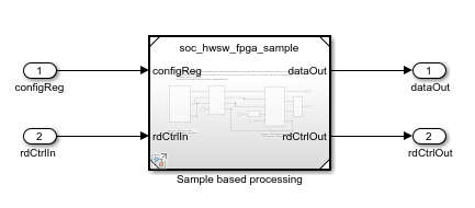
In the new model, using Stream Connector block, SoC Bus Selector block, SoC Bus Creator block, and Subsystem blocks, create the following system.

Note
The signals for
rdCtrlInandrdCtrlOutmust use bus signal types set toStreamS2MBusObjandStreamM2SBusObj, respectively.Tip
When your FPGA model includes more than one IP, you must define each IP as a subsystem and connect the subsystems using a Stream Connector or Video Stream Connector block. For additional information, see Considerations for Multiple IPs in FPGA Model.
In the SoC Bus Creator block dialog mask, set Control type to
Valid.The
Test Sourcesubsystem simulates a free-running counter. Open theTest Sourcesubsystem and create the following system.
Note
The sources,
All data is validandNo-Op Tlast, must produce a signal withbooleandata type.

The
FPGA Algorithmsubsystem simulates the multiplication of streamed data. Open theFPGA Algorithmsubsystem and using an Enabled Subsystem, Logical Operator, and Data Type Conversion blocks, create the following system.
Top Model
The Stream from FPGA to Processor Template, the FPGA subsystem uses a model variant to select between the sample based model developed in this section and a frame based model. The frame based model allows faster simulations but does not support code generation.
See Also
Stream Connector | SoC Bus Selector | SoC Bus Creator