Customizing SerDes Toolbox Datapath Control Signals
This example shows how to customize the control signals in a SerDes system datapath by adding new custom AMI parameters and using MATLAB® function blocks. This allows you to customize existing control parameters without modifying the built-in blocks in the SerDes Toolbox™ library.
This example shows how to add a new AMI parameter to control the operation of the three transmitter taps used by the FFE block. The custom AMI parameter simultaneously sets all three taps to one of the ten values defined by the PCIe4 specification or allows you to enter three custom floating-point tap values. To know more about how to define a PCIe4 transmitter model, see PCIe4 Transmitter/Receiver IBIS-AMI Model.
PCIe4 Transfer Model
The transmitter model in this example complies with the PCIe4 specification. The receiver is a simple pass-through model. A PCIe4 compliant transmitter uses a 3-tap feed forward equalizer (FFE) with one pre-tap and one post-tap, and ten presets.
Open the model adding_tx_ffe_params. The SerDes system Simulink® model consists of Configuration, Stimulus, Tx, Analog Channel, and Rx blocks.
open_system('adding_tx_ffe_params.slx')
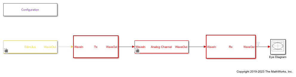
The Tx subsystem contains an FFE block to model the time-domain portion of the AMI model and an Init block to model the statistical portion.
The Analog Channel block has the PCIe4 parameter values for Target frequency, Loss, Impedance, and Tx/Rx analog model parameters.
The Rx subsystem has a Pass-Through block and an Init block.
Add New AMI Parameter
Add a new AMI parameter to the transmitter which is available to both the Init and GetWave datapath blocks and functions. The parameter is also included in the Tx IBIS-AMI file.
Double-click the Configuration block to open the Block Parameters dialog box. Click the Open SerDes IBIS-AMI Manager button. Go to the AMI-Tx tab of the SerDeS IBIS-AMI Manager dialog box.
Select the FFE parameter, then click Add Parameter... to add a new FFE sub-parameter.
Set the Parameter name to
ConfigSelect.Keep the Current value as
0.In the Description, add
Pre/Main/Post tap configuration selector.Keep the Usage as
In.Set the Type to
Integer.Set the Format to
List.Under the List Format details, set Default to
0.Set List values to
[-1 0 1 2 3 4 5 6 7 8 9]Set List_Tip values to
["User Defined" "P0" "P1" "P2" "P3" "P4" "P5" "P6" "P7" "P8" "P9"]
A new parameter ConfigSelect is added to the AMI-Tx tab.
Modify Init
Modify the Initialize MATLAB function inside the Init block in the Tx subsystem to use the newly added ConfigSelect parameter. The ConfigSelect parameter controls the existing three transmitter taps. To accomplish this, add a switch statement that takes in the values of ConfigSelect and automatically sets the values for all three Tx taps, ignoring the user defined values for each tap. If a ConfigSelect value of -1 is used, then the user-defined Tx tap values are passed through to the FFE datapath block unchanged.
Inside the Tx subsystem, double-click the Init block to open the Block Parameters dialog box and click the Refresh Init button to propagate the new AMI parameter to the Initialize sub-system.
Type Ctrl-U to look under the mask for the Init block, then double-click on the initialize block to open the Initialize Function.
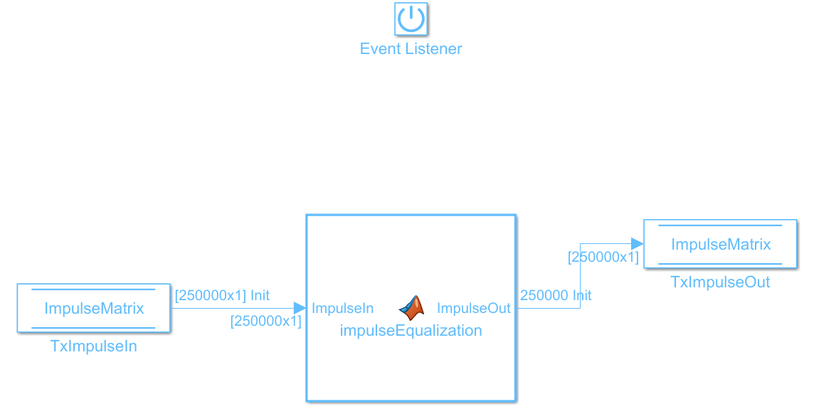
Double-click on the impulseEqualization MATLAB function block to open the function in MATLAB. This is an automatically generated function which provides the impulse response processing of the SerDes system block (IBIS AMI-Init). The %% BEGIN: and % END: lines denote the section where custom user code can be entered. Data in this section will not get over-written when Refresh Init is run:
%% BEGIN: Custom user code area (retained when 'Refresh Init' button is pressed)
FFEParameter.ConfigSelect; % User added AMI parameter
% END: Custom user code area (retained when 'Refresh Init' button is pressed)
To add the custom ConfigSelect control code, scroll down the Customer user code area, comment out the FFEParameter.ConfigSelect line, then enter the following code:
%% BEGIN: Custom user code area (retained when 'Refresh Init' button is pressed)
%FFEParameter.ConfigSelect; % User added AMI parameter
switch FFEParameter.ConfigSelect
case -1  % User defined tap weights
FFEInit.TapWeights = FFEParameter.TapWeights;
case 0  % PCIe Configuration: P0
FFEInit.TapWeights = [0.000 0.750 -0.250];
case 1  % PCIe Configuration: P1
FFEInit.TapWeights = [0.000 0.830 -0.167];
case 2  % PCIe Configuration: P2
FFEInit.TapWeights = [0.000 0.800 -0.200];
case 3  % PCIe Configuration: P3
FFEInit.TapWeights = [0.000 0.875 -0.125];
case 4  % PCIe Configuration: P4
FFEInit.TapWeights = [0.000 1.000 0.000];
case 5  % PCIe Configuration: P5
FFEInit.TapWeights = [-0.100 0.900 0.000];
case 6  % PCIe Configuration: P6
FFEInit.TapWeights = [-0.125 0.875 0.000];
case 7  % PCIe Configuration: P7
FFEInit.TapWeights = [-0.100 0.700 -0.200];
case 8  % PCIe Configuration: P8
FFEInit.TapWeights = [-0.125 0.750 -0.125];
case 9  % PCIe Configuration: P9
FFEInit.TapWeights = [-0.166 0.834 0.000];
otherwise
FFEInit.TapWeights = FFEParameter.TapWeights;
end
% END: Custom user code area (retained when 'Refresh Init' button is pressed)
To test that the new FFE control parameter is working correctly, open the SerDes IBIS-AMI Manager dialog box from the Configuration block. In the AMI-Tx tab, edit the ConfigSelect parameter to set Current value to P7. This corresponds to PCIe Configuration P7: Pre = -0.100, Main = 0.700 and Post = -0.200.
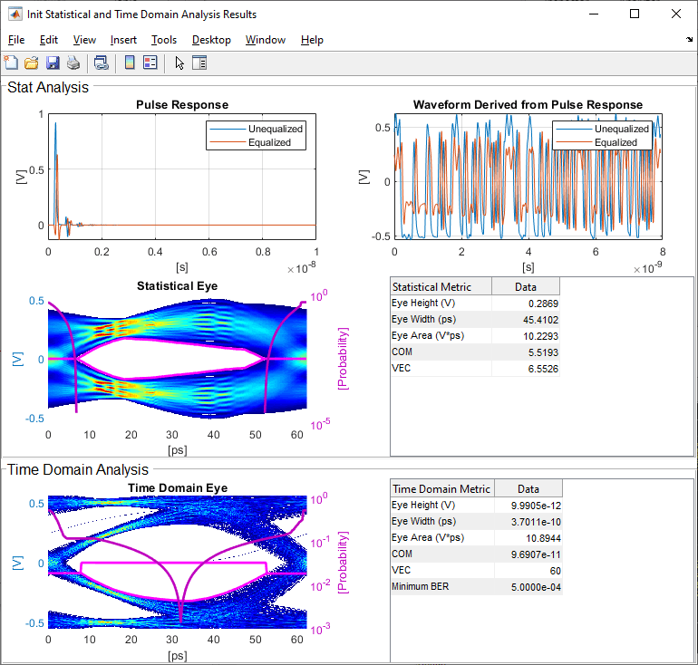
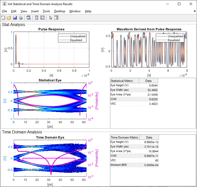
Run the simulation and observe the results of Init statistical analysis. Note: The Time Domain waveform will not be correct until you wire the Constant block for the new parameter ConfigSelect in the canvas for the FFE. You will see how to do this in the next section.
Next, set the Current value of the ConfigSelect parameter to User Defined. This corresponds to user-defined tap weights: Pre = 0.000, Main = 1.000 and Post = 0.000.
Run the simulation and observe the results of Init statistical analysis.

Try different values of ConfigSelect to verify proper operation. The statistical eye opens and closes based on the amount of equalization applied by the FFE. How much the eye changes, and the tap values that create the most open eye varies based on the loss defined in the Analog Channel block.
Modify GetWave
To modify GetWave, add a new MATLAB function that operates in the same manner as the Initialize function.
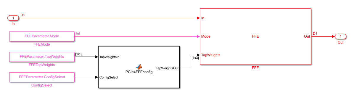
Inside the Tx subsystem, type Ctrl-U to look under the mask of the FFE block.
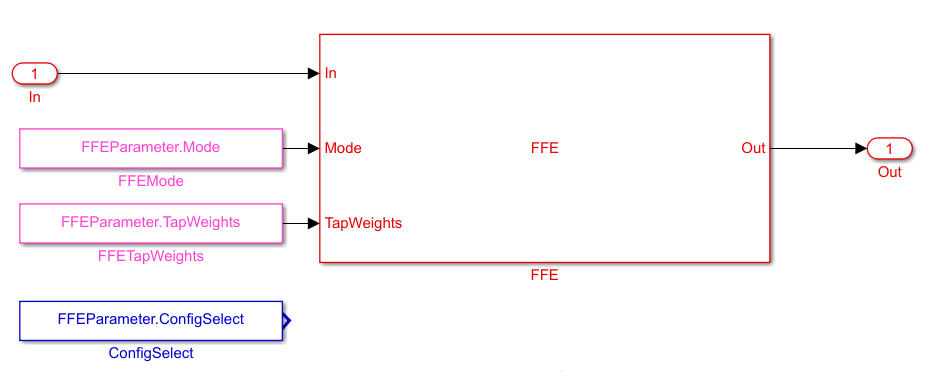
You can see that a Constant block was automatically added by the IBIS-AMI manager to the canvas with the Constant value set to
FFEParameter.ConfigSelect.Add a MATLAB Function block to the canvas from the Simulink/User-Defined library.
Rename the MATLAB Function block to
PCIe4FFEconfig.Double-click the MATLAB Function block and replace the template code with the following:
% PCIe4 tap configuration selector
%   Selects pre-defined Tx FFE tap weights based on PCIe4 specified
%   configurations.
%
% Inputs:
%   TapWeightsIn: User defined floating point tap weight values.
%   ConfigSelect: 0-9: PCIe4 defined configuration (P0-P9).
%                 -1:  User defined configuration (from TapWeightsIn).
% Outputs:
%   TapWeightsOut: Array of tap weights to be used.
%
function TapWeightsOut = PCIe4FFEconfig(TapWeightsIn, ConfigSelect)
switch ConfigSelect
    case -1  % User defined tap weights
         TapWeightsOut = TapWeightsIn;
    case 0   % PCIe Configuration: P0
        TapWeightsOut = [0.000 0.750 -0.250];
    case 1   % PCIe Configuration: P1
        TapWeightsOut = [0.000 0.833 -0.167];
    case 2   % PCIe Configuration: P2
         TapWeightsOut = [0.000 0.800 -0.200];
    case 3   % PCIe Configuration: P3
        TapWeightsOut = [0.000 0.875 -0.125];
    case 4   % PCIe Configuration: P4
        TapWeightsOut = [0.000 1.000 0.000];
    case 5   % PCIe Configuration: P5
        TapWeightsOut = [-0.100 0.900 0.000];
    case 6   % PCIe Configuration: P6
        TapWeightsOut = [-0.125 0.875 0.000];
    case 7   % PCIe Configuration: P7
        TapWeightsOut = [-0.100 0.700 -0.200];
    case 8   % PCIe Configuration: P8
        TapWeightsOut = [-0.125 0.750 -0.125];
    case 9   % PCIe Configuration: P9
         TapWeightsOut = [-0.166 0.834 0.000];
    otherwise
         TapWeightsOut = TapWeightsIn;
end
Re-wire the FFE sub-system so that the FFETapWeights and FFEConfigSelect constant blocks connect to the inputs of the newly defined PCIe4FFEconfig MATLAB function block. The TapWeightsOut signal from the PCIe4FFEconfig block connects to the TapWeights port of the FFE block.
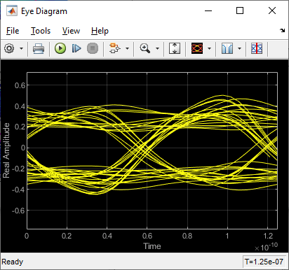
To test that the new FFE control parameter is working correctly, open the SerDes IBIS-AMI Manager dialog box from the Configuration block. In the AMI-Tx tab, edit the ConfigSelect parameter to set Current value to P7. This corresponds to PCIe Configuration P7: Pre = -0.100, Main = 0.700 and Post = -0.200. Observe the output waveform.

Next, set the Current value of the ConfigSelect parameter to User Defined. This corresponds to user-defined tap weights: Pre = 0.000, Main = 1.000 and Post = 0.000. Observe how the output waveform changes.
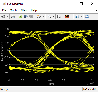
Try different values of ConfigSelect to verify proper operation. The time-domain eye opens and closes based on the amount of equalization applied by the FFE. How much the eye changes, and the tap values that create the most open eye varies based on the loss defined in the Analog Channel block.
Export the Tx IBIS-AMI Model
Verify that both Init and GetWave are behaving as expected, then generate the final IBIS-AMI compliant PCIe4 model executables, IBIS and AMI files.
Double-click the Configuration block to open the Block Parameters dialog box. Click the Open SerDes IBIS-AMI Manager button, then select the Export tab:
Update the Tx model name to
pcie4_tx.Tx and Rx corner percentage is set to
10. This will scale the min/max analog model corner values by +/-10%.Verify that Dual model is selected as Model Type for the Tx. This will create model executables that support both statistical (Init) and time domain (GetWave) analysis.
Set the Tx model Bits to ignore parameter to
3since there are three taps in the Tx FFE.Set the Models to export to Tx only.
Set the IBIS file name (.ibs) to
pcie4_tx_serdes.ibsClick the Export button to generate models in the Target directory.
Test Generated IBIS-AMI Model
The PCIe4 transmitter IBIS-AMI model is now complete and ready to be tested in any industry standard AMI model simulator.
References
See Also
FFE | PassThrough | SerDes Designer