Managing AMI Parameters
This example shows how to add, delete, modify, rename, and hide AMI parameters for an IBIS-AMI model built with SerDes Toolbox™. These AMI parameters are then available to be used with existing datapath blocks, user-created MATLAB® function blocks or optimization control loop, and can be passed to or returned from the AMI model executables (DLLs) created by SerDes Toolbox.
Example Setup
This example will be adding a new InOut Parameter 'Count' alongside the Pass-through datapath block. This parameter will count the number of passes through AMI_Init (which should be 1), then pass the result to AMI_GetWave where it will continue to count the total number of passes. While this may not be especially useful functionality for AMI model development, it will serve to demonstrate how new AMI parameters are added and used during model generation.
Inspect the Model
This example starts with a simple receiver model that only uses a pass-through block.
open_system('serdes_add_param.slx')

This Simulink® SerDes System consists of Configuration, Stimulus, Tx, Analog Channel and Rx blocks.
The Tx subsystem has the FFE datapath block to model the time domain portion of the AMI model and an Init block to model the statistical portion. The Tx subsystem will not be used in this example.
The Analog Channel block has the parameter values for Target frequency, Loss, Impedance and Tx/Rx analog model parameters.
The Rx subsystem has the Pass-Through datapath block and an Init block to model the statistical portion of the AMI model.
Run the Model
Run the model to verify that the base configuration is working as expected before editing. Two plots are generated. The first is a live time domain (GetWave) eye diagram that is updated as the model is running.

The second plot contains views of the results from statistical (Init) and time domain (GetWave) simulation.

Add New Parameter
Open the Block Parameter dialog box for the Configuration block, then click on the Open SerDes IBIS-AMI Manager button and select the AMI-Rx tab.
1. Highlight the PT datapath block and press Add Parameter...
2. Change the Parameter Name to: Count
3. Verify that the Current value is set to 0 (this will be the starting point for our count).
4. In the Description, type: Starting value of iteration count.
There are four possible values for Usage:
In: These parameters are required inputs to the AMI Executable.Out: These parameters are output from the AMI_Init and/or AMI_GetWave functions and returned to the EDA tool.InOut: These parameters are required inputs to the AMI Executable and can also return values from AMI_Init and/or AMI_GetWave to the EDA tool.Info: These parameters are information for the User and/or the simulation tool and are not used by the model.
5. Set the Usage to: InOut
There are six possible parameter Types:
Float: A floating point number.Integer: Integer numbers without a fractional or decimal component.UI: Unit Interval (the inverse of the data rate frequency).Tap: A floating point number for use by Tx FFE and Rx DFE delay lines.Boolean: True and False values, without quotation marks.String: A sequence of ASCII characters enclosed in quotation marks.
6. Set the Type to: Integer
There are three possible parameter Formats:
Value: A single data value.List: A discrete set of values from which the user may select one value.Range: A continuous range for which the user may select any value between Min and Max.
7. Set the Format to: Value
8. Click OK to create the new parameter, then you will see the new blocks automatically placed on the canvas.
Access New Parameter from Initialize Function
New parameters are accessed from the Initialize function (for statistical analysis) through the impulseEqualization MATLAB function block. This example has added an InOut parameter. To use the new InOut Parameter 'Count' in AMI_Init:
1. Inside the Rx subsystem, double click on the Init block to open the mask.
2. Press the Refresh Init button to propagate the new AMI parameter(s) to the initialize subsystem.
3. Click OK to close the mask.
4. Click on the Init block again and type Ctrl-U to look under the Init mask, then double-click on the initialize block to open the Initialize Function.
The impulseEqualization MATLAB function block is an automatically generated function which provides the impulse response processing of the SerDes system block (IBIS-AMI Init).
Note that the new Count parameter has been automatically added as an output of this MATLAB function as a Data Store Write block. No Data Store Read is required because the input parameters are passed in as a PTSignal Simulink.Parameter.

5. Double-click on the impulseEqualization MATLAB function block to open the function in MATLAB. The '%% BEGIN:' and '% END:' lines within this function block denote the section where custom user code can be entered. Data in this section will not get over-written when Refresh Init is run:
%% BEGIN: Custom user code area (retained when 'Refresh Init' button is pressed)
% END: Custom user code area (retained when 'Refresh Init' button is pressed)
When Refresh Init was run, it added our new parameter to the Custom user code area so that it can be used as needed:
%% BEGIN: Custom user code area (retained when 'Refresh Init' button is pressed)
PTCount = PTParameter.Count; % User added AMI parameter from SerDes IBIS-AMI Manager
% END: Custom user code area (retained when 'Refresh Init' button is pressed)
6. To add our custom code, scroll down to the Custom user code section, then enter PTCount = PTCount + 1; The Custom user code section should look like this:
%% BEGIN: Custom user code area (retained when 'Refresh Init' button is pressed)
PTCount = PTParameter.Count; % User added AMI parameter from SerDes IBIS-AMI Manager
PTCount = PTCount + 1;  % Count each iteration through this function.
% END: Custom user code area (retained when 'Refresh Init' button is pressed)
7. Save the updated MATLAB function, then run the Simulink project to test the new code. Using the Simulation Data Inspector, verify that the value of Count after Init is now '1'.
Note that the final value for Count was written to the PTSignal data store so that it is now available in AMI_GetWave.
Effect of Usage on Parameters in Init
Depending on what Usage was selected, parameters show up in the Custom User code area of the impulseEqualization MATLAB function block in different ways:
Info Parameters
Info parameters are informational for the user or simulation tool and are not passed to, or used by the model, therefore they will not show up in the Initialize code.
In Parameters
In parameters are Simulink.Parameter objects that show up as a constant that can be used as needed. For example, an In parameter named 'InParam' that was added to the VGA block would show up as follows:
VGAParameter.InParam; % User added AMI parameter from SerDes IBIS-AMI Manager
Out Parameters
Out parameters are Simulink.Signal objects that show up as a parameter with the initial value defined in the IBIS-AMI Manager. For example, an Out parameter named 'OutParam' that was added to the VGA block with a current value of '2' would show up as follows:
VGAOutParam=2; % User added AMI parameter from SerDes IBIS-AMI Manager
Output parameters use a Data Store Write block to store values for passing out of Init to the EDA tool (via the AMI_Parameters_Out string) and for use in GetWave (if desired). In the above example, a Data Store Write block named 'OutParam' was automatically added to the Initialize Function:

InOut Parameters
InOut parameters use both a Simulink.Parameter object and a Simulink.Signal object. For example, an InOut parameter named 'InOutParam' that was added to the VGA block would show up as follows:
VGAInOutParam = VGAParameter.InOutParam; % User added AMI parameter from SerDes IBIS-AMI Manager
The Input value is accessed by using the Simulink.Parameter reference VGAParameter.InOutParam, while the output value uses a Data Store Write block to store values. In the above example, a Data Store Write block named 'InOutParam' was automatically added to the Initialize Function for passing values out of Init to the EDA tool (via the AMI_Parameters_Out string) and for use in GetWave (if desired):

Access New Parameter from the GetWave Function
New parameters are automatically created as blocks of type Constant, Data Store Read or Data Store Write and added to the canvas of a datapath block. This example has added an InOut parameter. To use the new InOut Parameter 'Count' in GetWave:
1. Inside the Rx subsystem, click on the Pass-Through datapath block and type Ctrl-U to look under the Pass-Through mask.

2. Add a Simulink/Math Operations Sum block to the canvas.
3. Add a Simulink/Sources Constant block to the canvas and set the value to 1.
4. Wire up each of the elements so that the Pass Through block now looks like the following:

7. Save, then run the Simulink project to test the new code.
By adding Value Labels to the output port of the Sum block, see that the value of Count after GetWave is 3.2e+04 (Samples Per Symbol * Number of symbols). After generating AMI model executables, the value of Count will be available in the Parameters out string in an AMI simulator.
Effect of Usage on Parameters in GetWave
New parameters are accessed from the GetWave function in different ways, depending on what Usage was selected.
Info Parameters
Info parameters are informational for the user or simulation tool and cannot be used by the model.
In Parameters
In parameters are Simulink.Parameter objects that are used by adding a Constant block. For example, an In parameter named 'InParam' that was added to the Rx VGA block can be accessed by any of the Rx blocks by adding a Constant block like this:

For more information, see Customizing SerDes Toolbox Datapath Control Signals.
Out Parameters
Out parameters are Simulink.Signal objects that use a Data Store Write block to store values for passing out of GetWave to the EDA tool (via the AMI_Parameters_Out string) or to other Rx blocks. For example, an Out parameter named 'OutParam' that was added to the Rx VGA block can be written to with a Data Store Write block like this:

InOut Parameters
InOut parameters use both a Simulink.Parameter object and a Simulink.Signal object. The Input value can be accessed with either a constant block or with a Data Store Read block, while the output value uses a Data Store Write block to store values for passing out of GetWave to the EDA tool (via the AMI_Parameters_Out string) or to other Rx blocks. For example, if an InOut parameter named 'InOutParam' is added to the Rx VGA block, the initial Input value can be accessed by any Rx block by adding a Constant block like this:

Alternately, the updated Input value can be accessed with a Data Store Read block like this:

The output value can be written to with a Data Store Write block like this:

Rename Existing Parameter
The parameters used by the SerDes Toolbox built-in System Objects can be modified or hidden but cannot be renamed.
User generated AMI parameters are renamed as follows.
Update the AMI Parameters
1. Open the Block Parameter dialog box for the Configuration block, then click on the Open SerDes IBIS-AMI Manager button.
2. Go to either the AMI-Tx or AMI-Rx tab where the parameter resides.
3. Highlight the parameter to be renamed and press Edit...
4. In the Parameter name field, changed the name as desired.
5. Click OK, then you will see the new parameters automatically renamed on the canvas.
Update Init
1. Push into either the Tx or Rx subsystem block where the parameter is used.
2. Double click on the Init block to open the mask.
3. Press the Refresh Init button to propagate the AMI parameter name change to the initialize subsystem.
4. Click OK to close the mask.
5. Click on the Init block again and type Ctrl-U to look under the Init mask, then double-click on the initialize block to open the Initialize Function.
6. Double-click on the impulseEqualization MATLAB function block to open the function in MATLAB.
7. Scroll down to the section titled:
%% BEGIN: Custom user code area (retained when 'Refresh Init' button is pressed)
8. You can confirm all instances of the parameter have been renamed.
9. Save and close the MATLAB function block.
Update GetWave
Push into each datapath block where the renamed parameter was used and rename each instance of the parameter.
Verify Results
Run a simulation to verify that the project still operates with no errors or warnings.
Delete Parameter
The parameters used by the SerDes Toolbox built-in System Objects can be modified or hidden but cannot be deleted.
User generated AMI parameters are deleted as follows.
Update the AMI Parameters
1. Open the Block Parameter dialog box for the Configuration block, then click on the Open SerDes IBIS-AMI Manager button.
2. Go to either the AMI-Tx or AMI-Rx tab where the parameter resides.
3. Highlight the parameter to be deleted and press Delete Parameter.
4. You will see the parameter blocks automatically removed from the canvas.
Update Init
Note: Parameters in the custom user code area are not automatically removed, so you will comment or delete them with the following steps:
1. Push into either the Tx or Rx subsystem block where the parameter was used.
2. Double click on the Init block to open the mask.
3. Press the Refresh Init button to remove any deleted Out or InOut parameter Data Stores from the initialize subsystem.
4. Click OK to close the mask.
5. Click on the Init block again and type Ctrl-U to look under the Init mask
6. Double-click on the initialize block to open the Initialize Function.
7. Double-click on the impulseEqualization MATLAB function block to open the function in MATLAB.
8. Scroll down to the section titled:
%% BEGIN: Custom user code area (retained when 'Refresh Init' button is pressed)
9. Delete or comment out all instances of the removed parameter.
10. Save and close the MATLAB function block.
Update GetWave
Push into each datapath block where the removed parameter was used and delete each instance of the parameter.
Verify Results
Run a simulation to verify that the project still operates with no errors or warnings.
Hide Parameter
There may be times when a parameter is required for model functionality, but needs to be hidden from the user. For example, to keep a user from changing the FFE mode, edit the FFE mode parameter and check the "Hidden" checkbox.
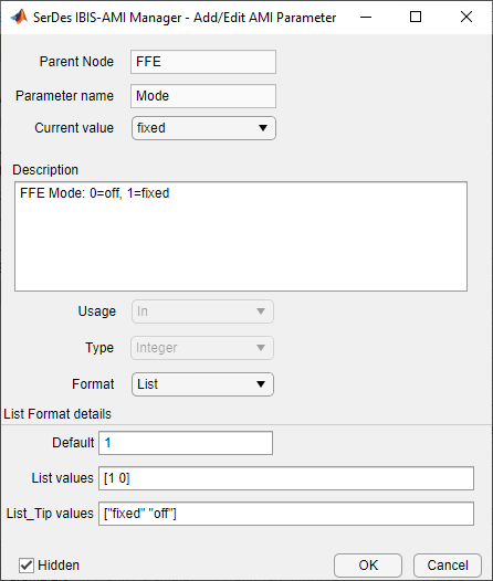
This will prevent this parameter from being present in the .ami file - effectively hardcoding the parameter to its default value. In other words, the FFE mode parameter is still present in the code so that the FFE continues to work as expected, but the user can no longer change the value.
To hide a parameter from both Init and GetWave:
1. Open the mask by double-clicking on the datapath block of interest.
2. Expand the IBIS-AMI parameters to show the list of parameters to be included in the IBIS-AMI model.
3. Deselect the parameter(s) to be hidden.
A few things to keep in mind about hiding parameters:
When hiding parameters, verify that the current parameter value(s) are correct. The current value will now always be used as the default value for that parameter.
Hiding a parameter has no effect on the model executable. It only removes the parameter from the generated .ami file.
If the hidden parameter is of type Out or InOut, it will still show up in the AMI_Parameters_Out string of the model executable.
Modify Parameter
All the parameters used in SerDes Toolbox are modified via the SerDes IBIS-AMI Manager dialog box by using the Edit... button. However, the parameter values that can be modified vary depending on which type of parameters they are.
For the built-in System Objects, only the following fields can be modified:
Current Value
Description
Format
Default
List values (for Format List)
Typ/Min/Max values (for Format Range)
For the user defined parameters all fields can be modified.
Add Reserved Parameters for Jitter, Analog Buffer Modeling, and Data Management
Reserved AMI parameters include:
Jitter and noise parameters such as Tx_Rj, Tx_Dj, Tx_DCD, Rx_Rj, Rx_Dj, Rx_DCD, Rx_GaussianNoise, and others
Analog buffer modeling parameters such as Ts4file, TX_V, and RX_R
Data management using DLL_ID
These are post-processing parameters that are used by an IBIS-AMI compliant simulator to modify the simulation results accordingly. These parameters are added via the SerDes IBIS-AMI Manager dialog box by using the Reserved Parameters... button on the AMI-Tx or AMI-Rx tabs.
Note: The reserved parameter AMI_Version will automatically change to 7.0 if any IBIS 7.0 reserved parameters are enabled in the IBIS-AMI Manager.
Note: Some of the reserved parameters only effects the exported IBIS-AMI model and is not included in Simulink simulation results. For more information, see Customize AMI Parameters.
For example, to add Rx_Receiver_Sensitivity and Rx_Dj to a receiver .ami file, click the Reserved Parameters... button to bring up the Rx Add/Remove Jitter & Noise dialog box, select the Rx_Receiver_Sensitivity and Rx_Dj boxes, then click OK to add these parameters to the Reserved Parameters section of the Rx AMI file.
To set the values for these two new parameters:
Select Rx_Receiver_Sensitivity, then click the Edit... button to open the Add/Edit AMI Parameter dialog box.
Set the Current Value to
0.04.Change the Format to
Value.Click OK to save the changes.
Select Rx_Dj, then click the Edit... button to bring up the Add/Edit AMI Parameter dialog box.
Set the Current Value to
0.0.Change the Type to
UI.Change the Format to
Range.Set the Typ value to
0.05.Set the Min value to
0.0.Set the Max value to
0.1.Click OK to save the changes.
These two parameters will appear in the Reserved_Parameters section of the .ami file as shown:
(Rx_Receiver_Sensitivity (Usage Info)(Type Float)(Value 0.04))
(Rx_Dj (Usage Info) (Type UI) (Range 0.05 0.0 0.01))
For another example, you can use Touchstone files (also known as SnP files) to customize analog buffer modeling of a transmitter or receiver. This option can be enabled using the reserved parameter Ts4file in the IBIS AMI Manager.

When you click the Export button in the IBIS AMI Manager, a dialog box will appear where you can select the s-parameter files for each process-corner model to support the reserved parameter Ts4file.

For more information on IBIS reserved parameters see the IBIS specification.
References
See Also
SerDes Designer | FFE | PassThrough