serdes.ChannelLoss
Create simple lossy transmission line model
Description
The serdes.ChannelLoss
System object™ constructs a lossy transmission line model for use in the SerDes Designer app
and other exported Simulink® models in the SerDes Toolbox™. For more information, see Analog Channel Loss in SerDes System.
To construct the loss model from channel loss metric:
Create the
serdes.ChannelLossobject and set its properties.Call the object with arguments, as if it were a function.
To learn more about how System objects work, see What Are System Objects?
Creation
Description
ChannelLoss = serdes.ChannelLossChannelLoss object that modifies an input waveform with a lossy printed
circuit board transmission line model according to the method outlined in [1].
ChannelLoss = serdes.ChannelLoss(Name,Value)
Example: ChannelLoss =
serdes.ChannelLoss('Loss',5,'TargetFrequency',14e9) returns a
ChannelLoss object that has a channel loss of 5 dB at 14
GHz.
Properties
Object Functions
To use an object function, specify the
System object as the first input argument. For
example, to release system resources of a System object named obj, use
this syntax:
release(obj)
Examples
This example shows how to process an ideal sinusoidal input waveform with the ChannelLoss model and check that it modifies the amplitude of the waveform in a reasonable way.
Define the system parameters. Use a symbol time of 100 ps with 8 samples per symbol. The amplitude of the input signal is 1 V. The channel loss is 3 dB.
SymbolTime = 100e-12;
SamplesPerSymbol = 8;
a0 = 1;
Loss = 3;
Calculate the sample interval. Define a time vector that is 30 symbols long.
dt = SymbolTime/SamplesPerSymbol;
t = (0:SamplesPerSymbol*30)*dt;
Create the sinusoidal input waveform.
F = 1/SymbolTime/2;      %Fundamental frequency
inputWave = a0*sin(2*pi*F*t);
Create the channelModel object at the specified loss for near ideal transmitter and receiver termination.
channelModel = serdes.ChannelLoss('Loss',Loss,'dt',dt,...
      'TargetFrequency',F,'TxR',50,'TxC',1e-14,...
      'RxR',50,'RxC',1e-14);
Process the input waveform using the channelModel object.
outputWave = channelModel(inputWave);
Calculate the output amplitudes.
a1 = max(outputWave);                              %Output amplitude
aideal = a0*10^(-abs(channelModel.Loss)/20);       %Theoretical output amplitude
Generate the frequency response.
s21 = channelModel.s21;
f = (0:length(s21)-1)*channelModel.dF;
Determine the loss at the target frequency of the frequency response.
f1 = find(f>channelModel.TargetFrequency,1,'first');
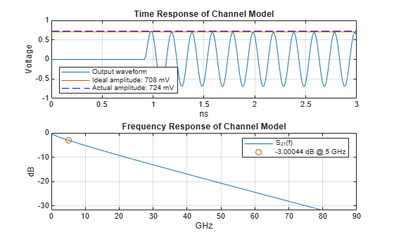
LossAtTarget = interp1(f(f1-1:f1),db(s21(f1-1:f1)),channelModel.TargetFrequency);Plot the time and frequency response of the channel model.
tns = t*1e9;
thline = [tns(1),tns(end)];
fghz = f*1e-9;
figure
subplot(211)
plot(tns,outputWave,thline,aideal*[1 1],thline,a1*[1 1],'b--'),
grid on
xlabel('ns'),ylabel('Voltage')
title('Time Response of Channel Model')
legend('Output waveform',...
sprintf('Ideal amplitude: %g mV',round(aideal*1e3)),...
sprintf('Actual amplitude: %g mV',round(a1*1e3)),'Location','southwest')
subplot(212)
plot(fghz,db(s21),...
channelModel.TargetFrequency*1e-9,LossAtTarget,'o')
title('Frequency Response of Channel Model')
legend('S_{21}(f)',sprintf('%g dB @ %g GHz',LossAtTarget,channelModel.TargetFrequency*1e-9))
grid on
xlabel('GHz')
ylabel('dB')
More About
ICN is a frequency domain metric where the crosstalk is multiplied by a weighting function and then numerically integrated from 50 MHz to the baud rate (fb). If there are multiple aggressors, their power are summed together before combining with the weighting function.
The time domain signal does not excite all frequencies evenly. The power spectral density (PSD) of a baseband time domain excitation follows a sinc-squared type response. The weighting function mimics the excitation of the PSD and shapes the PSD by including the effects of the receiver bandwidth and the transmitter rise time.

The total ICN is calculated by root-sum-squaring the FEXT ICN and NEXT ICN values together.
Algorithms
To obtain a lossy printed circuit board (PCB) transmission line (T-line) model with a
given Loss at the TargetFrequency, two T-lines of length 100 mm and 150
mm are created and loss evaluated at the Target Frequency. These two data points are used to
extrapolate to the transmission line length needed to achieve the requested loss. The
transmission line model is an analytic equation based on the method described in [1].
This transmission line, with the requested loss is then combined with the Tx and Rx single ended termination resistance and capacitance as illustrated below:

References
[1] IEEE 802.3bj-2014. "IEEE Standard for Ethernet Amendment 2: Physical Layer Specifications and Management Parameters for 100 Gb/s Operation Over Backplanes and Copper Cables." https://standards.ieee.org/standard/802_3bj-2014.html.
[2] Stephen Hall and Howard Heck. Advanced Signal Integrity for High-Speed Digital Designs. Hoboken, NJ: Wiley Press, 2009.
Extended Capabilities
Version History
Introduced in R2019a