plan
Plan path using RRT for manipulators
Syntax
Description
path = plan(rrt,startConfig,goalConfig)rrt.
path = plan(rrt,startConfig,goalRegion)workspaceGoalRegion object
Examples
Use the manipulatorRRT object to plan a path for a rigid body tree robot model in an environment with obstacles. Visualize the planned path with interpolated states.
Load a robot model into the workspace. Use the KUKA LBR iiwa© manipulator arm.
robot = loadrobot("kukaIiwa14","DataFormat","row");
Generate the environment for the robot. Create collision objects and specify their poses relative to the robot base. Visualize the environment.
env = {collisionBox(0.5, 0.5, 0.05) collisionSphere(0.3)};
env{1}.Pose(3, end) = -0.05;
env{2}.Pose(1:3, end) = [0.1 0.2 0.8];

show(robot);
hold on
show(env{1})
show(env{2})
Create the RRT planner for the robot model.
rrt = manipulatorRRT(robot,env);
rrt.SkippedSelfCollisions = "parent";
Specify a start and a goal configuration.
startConfig = [0.08 -0.65 0.05 0.02 0.04 0.49 0.04];
goalConfig =  [2.97 -1.05 0.05 0.02 0.04 0.49 0.04];
Plan the path. Due to the randomness of the RRT algorithm, set the rng seed for repeatability.
rng(0)
path = plan(rrt,startConfig,goalConfig);
Visualize the path. To add more intermediate states, interpolate the path. By default, the interpolate object function uses the value of ValidationDistance property to determine the number of intermediate states. The for loop shows every 20th element of the interpolated path.
interpPath = interpolate(rrt,path);
clf
for i = 1:20:size(interpPath,1)
    show(robot,interpPath(i,:));
    hold on
end
show(env{1})
show(env{2})
hold off

Specify a goal region in your workspace and plan a path within those bounds. The workspaceGoalRegion object defines the bounds on the xyz-position and zyx Euler orientation of the robot end effector. The manipulatorRRT object plans a path based on that goal region and samples random poses within the bounds.
Load an existing robot model as a rigidBodyTree object.
robot = loadrobot("kinovaGen3", "DataFormat", "row");
ax = show(robot);

Create Path Planner
Create a rapidly-exploring random tree (RRT) path planner for the robot. This example uses an empty environment, but this workflow also works well with cluttered environments. You can add collision objects to the environment like the collisionBox or collisionMesh object.
planner = manipulatorRRT(robot,{});
planner.SkippedSelfCollisions="parent";
Define Goal Region
Create a workspace goal region using the end-effector body name of the robot.
Define the goal region parameters for your workspace. The goal region includes a reference pose, xyz-position bounds, and orientation limits on the zyx Euler angles. This example specifies bounds on the xy-plane in meters and allows rotation about the z-axis in radians.
goalRegion = workspaceGoalRegion(robot.BodyNames{end});
goalRegion.ReferencePose = trvec2tform([0.5 0.5 0.2]);
goalRegion.Bounds(1, :) = [-0.2 0.2];    % X Bounds
goalRegion.Bounds(2, :) = [-0.2 0.2];    % Y Bounds
goalRegion.Bounds(4, :) = [-pi/2 pi/2];  % Rotation about the Z-axis
You can also apply a fixed offset to all poses sampled within the region. This offset can account for grasping tools or variations in dimensions within your workspace. For this example, apply a fixed transformation that places the end effector 5 cm above the workspace.
goalRegion.EndEffectorOffsetPose = trvec2tform([0 0 0.05]);
hold on
show(goalRegion);
Plan Path To Goal Region
Plan a path to the goal region from the robot's home configuration. Due to the randomness in the RRT algorithm, this example sets the rng seed to ensure repeatable results.
rng(0)
path = plan(planner,homeConfiguration(robot),goalRegion);
Show the robot executing the path. To visualize a more realistic path, interpolate points between path configurations.
interpConfigurations = interpolate(planner,path,5);

for i = 1:size(interpConfigurations,1)
    show(robot,interpConfigurations(i,:),"PreservePlot",false);
    set(ax,'ZLim',[-0.05 0.75],'YLim',[-0.05 1],'XLim',[-0.05 1],...
        'CameraViewAngle',5)

    drawnow
end
hold off

Adjust End-Effector Pose
Notice that the robot arm approaches the workspace from the bottom. To flip the orientation of the final position, add a pi rotation to the Y-axis for the reference pose.
goalRegion.EndEffectorOffsetPose = ...
    goalRegion.EndEffectorOffsetPose*eul2tform([0 pi 0],"ZYX");
Replan the path and visualize the robot motion again. The robot now approaches from the top.
hold on
show(goalRegion);
path = plan(planner,homeConfiguration(robot),goalRegion);

interpConfigurations = interpolate(planner,path,5);

for i = 1 : size(interpConfigurations,1)
    show(robot, interpConfigurations(i, :),"PreservePlot",false);
    set(ax,'ZLim',[-0.05 0.75],'YLim',[-0.05 1],'XLim',[-0.05 1])
    drawnow;
end
hold off

Load a KINOVA® Gen3 robot and create a workspace goal region for the end-effector link of the robot.
rbt = loadrobot("kinovagen3",DataFormat="row");
eename = "EndEffector_Link";
wgr1 = workspaceGoalRegion(eename);
wgr1.ReferencePose = trvec2tform([0.5 0 0.2]);
wgr1.Bounds(1:2,:) = [-0.2 0.2; -0.1 0.1];
wgr1.Bounds(4,:) = [-pi pi];
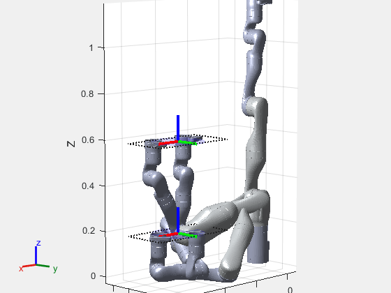
Create another workspace goal region with the same bounds as the first goal region but offset the goal region by 0.4 meters on the z-axis.
wgr2 = wgr1;
wgr2.ReferencePose = wgr1.ReferencePose*trvec2tform([0 0 0.4]);
Show the robot and the workspace goal regions.
show(rbt,homeConfiguration(rbt),Frames="off");
hold on
show(wgr1);
show(wgr2);
title("Robot with Two Workspace Goal Regions")
axis equal
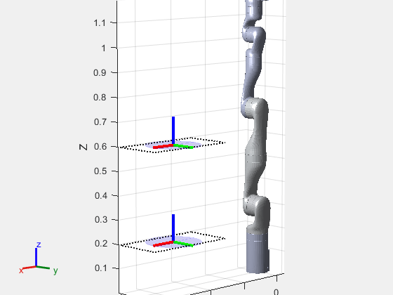
Create the RRT planner with an empty environment.
env = {};
planner = manipulatorRRT(rbt,env,skip="parent");
Plan a paths to the workspace goal regions. Note that the RRT planner samples goal configurations uniformly from the two goal regions.
rng(60)

for i = 1:4
    plannedpath = plan(planner,homeConfiguration(rbt),{wgr1,wgr2});
    show(rbt,plannedpath(end,:),Frames="off");
end
axis equal
title("Goal Configurations in Workspace Goal Regions")
hold off