Design Speed Control Algorithm
Use these steps to design a speed control algorithm:
Create a speed controller subsystem. The current controller subsystem that you created earlier uses the
Iq_refcurrent output of the speed controller subsystem as an input.To create a speed controller subsystem, open the Simulink® Library Browser and select the Discrete PI Controller with anti-windup & reset block from the
Motor
                            Control Blockset/Controls/Controllers
library.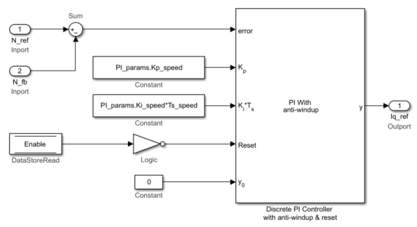
The MATLAB® function
mcb.getPIControllerParameters(in the model initialization script) calculates the PI control gains for the d-axis and q-axis current controller and the speed controller. For details about calculation of the controller gains, see Estimate Control Gains and Tune Control Parameters. For example, see the model initialization script filemcb_pmsm_foc_qep_f28379d_data.m(used in the example Field-Oriented Control of PMSM Using Quadrature Encoder) that uses a sampling time (Ts_speed) of500μs. Optionally, you can use the Enable Data-Store Memory block to reset the controller.Create a subsystem for the speed controller and add Rate Transition blocks (from the
Simulink/Signal
                            Attributes
library) to the subsystem inputs with a sample time of Ts_speed (execution time of the speed control loop).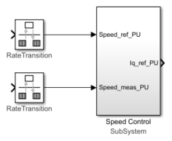
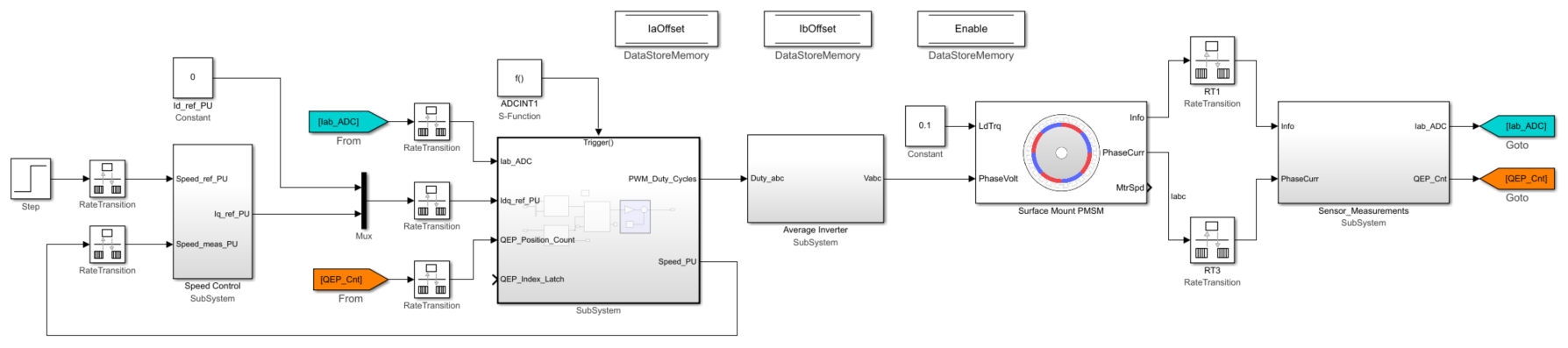
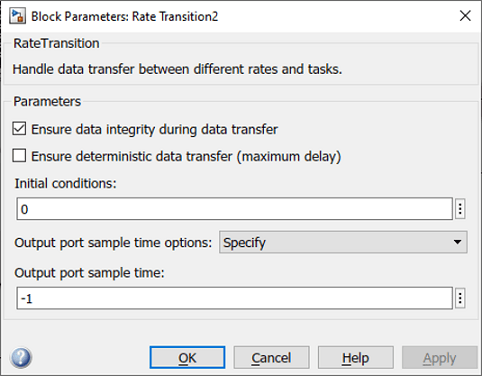
Integrate the speed controller subsystem (that you created in step 2) with the integrated current controller and plant model subsystems. Connect the Iq_ref_PU output port of the speed controller subsystem to the current controller subsystem input port through a Rate Transition block. The Rate Transition block is needed because the two ports execute at different sample rates. This figure shows an example of the parameter settings of the Rate Transition block connected to the speed controller and the current controller subsystems.
This figure shows the integrated speed controller, current controller, and plant model subsystems.