Dwell Angle Computation for SRM Speed Control
This example shows how to compute the dwell angle of a 12/8 switched reluctance motor (SRM) online (while the motor runs). The example then uses the computed dwell angle along with a delta controller to control the motor speed.
SRMs need commutation switching sequences to run. These sequences determine when the motor phases switch on and off, so they can run the motor while controlling the motor speed. Each commutation switching sequence (which forms a pulse train) can be used to control (turn on and off) the corresponding motor phase. The activation period defined by the turn-on ( ) and turn-off (
 ) angles is known as the dwell angle.
The dwell angle is one of the control variables for the motor. The optimal dwell angle depends on the motor parameters and the control objective.
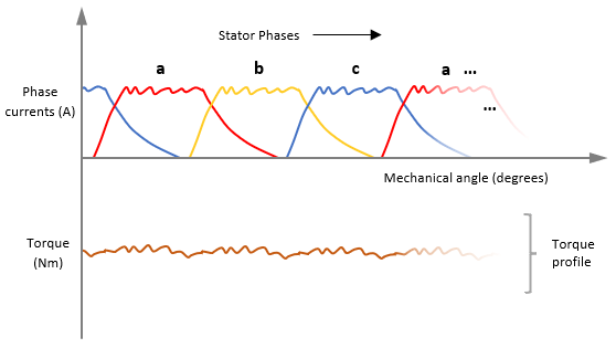
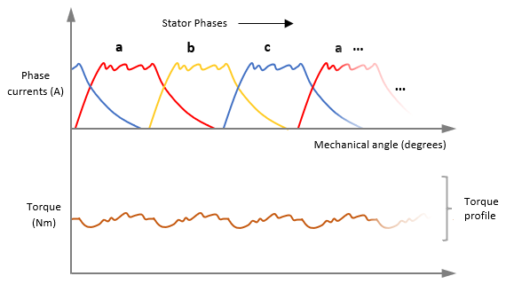
A large dwell angle yields smaller torque ripples and enhanced motor performance. However, because the phase current pulses overlap, it leads to greater power consumption, and therefore, makes the motor less energy efficient.
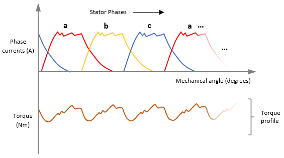
A small dwell angle is more energy efficient because of lower power consumption due to a reduced overlap of the phase current pulses. However, the larger torque ripples can degrade motor performance.
In this example, you compute an optimal dwell angle that balances motor energy efficiency and motor torque ripple amplitude. For a given reference speed and load condition, the example computes an optimal dwell angle using only a few SRM design parameters.
The following image shows an example torque profile corresponding to an optimized dwell angle.
The example computes the dwell angle using the angles  and
and  , as shown below.
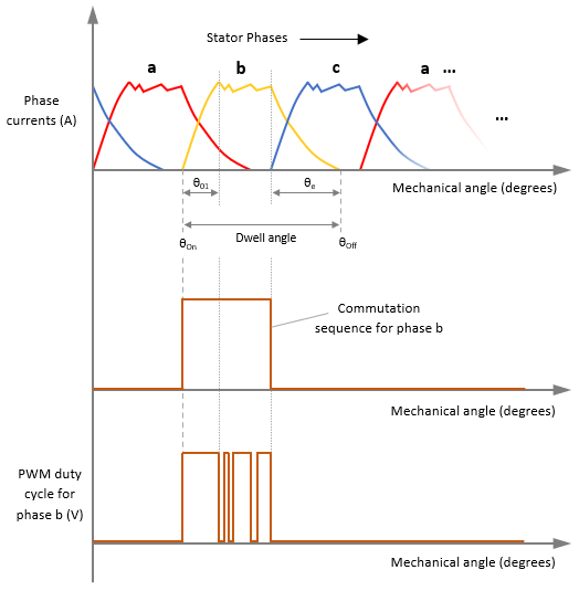
is the angle measured between phase activation and the point when the initial rise in phase current ends. is the angle measured between phase shutdown and the point when the phase current is zero. For a given phase, usually > due to the rising inductance profile in an SRM.
Note: The example computes and only for phase A, and assumes that all the phases behave identically.
The example model uses a PI controller (for speed control) and a delta controller (for current control), along with an online dwell angle computation algorithm to optimize the performance of the SRM. The low-runtime delta controller is easy-to-implement and computationally inexpensive. The current control loop runs at 50kHz (20µs). In addition, the example uses the necessary filters to enable smoother transitions for and .
Note: Using online dwell angle computation to control the SRM speed might reduce the range of achievable torque and speed.
Alternatively, you can use this example to run the SRM with a delta current controller using a fixed dwell angle by specifying and in the model initialization script.
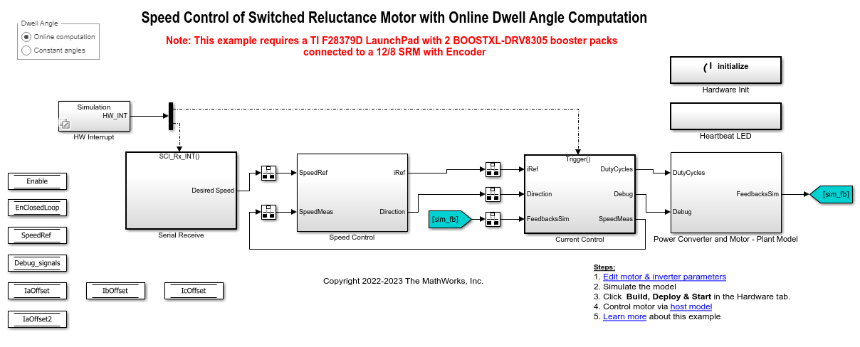
Model
The example includes the model mcb_srm_dwellctrl_f28379d.
You can use the model for both simulation and code generation.
For details about the supported hardware configuration, see Required Hardware in the Generate Code and Deploy Model to Target Hardware section.
Required MathWorks Products
To simulate model:
Motor Control Blockset™
Simscape™ Electrical™
To generate code and deploy model:
Motor Control Blockset™
Fixed-Point Designer™ (only needed for optimized code generation)
Embedded Coder®
C2000™ Microcontroller Blockset
Prerequisites
This example uses default SRM parameters. If you adapt this example to your own application or for your own hardware, replace these SRM parameters in the model initialization script. For instructions, see Estimate Control Gains and Tune Control Parameters.
PWM_frequency— Enter the switching frequency of the pulse-width modulation (PWM). Note that you might need to tune controller gains again if you change this value.
KpandKi— Enter the PI controller gains. Note that the example does not automatically compute these values. Set these gains according to the hardware setup.
thetaON— Enter the motor phase turn-on electrical position at which the switching sequence turns 0 to 1 and energizes the corresponding phase. The model uses this value only when you set the Dwell Angle button in the target model toConstant angles.
thetaOFF— Enter the motor phase turn-off electrical position at which the switching sequence turns 1 to 0 and de-energizes the corresponding phase. The model uses this value only when you set the Dwell Angle button in the target model toConstant angles.
Note: The example supports only single data type and per-unit computation.
Simulate Model
This example supports simulation. Follow these steps to simulate the model.
1. Open the target model included with this example.
2. Click Run on the Simulation tab to simulate the model.
3. Click Data Inspector on the Simulation tab to view and analyze the simulation results.
Generate Code and Deploy Model to Target Hardware
This section shows how to generate code and run the control algorithm on the target hardware.
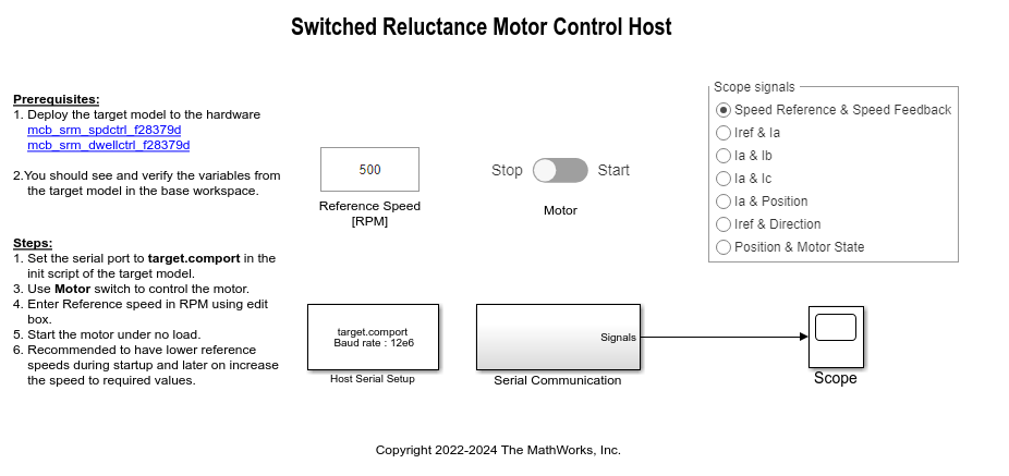
This example uses a host and a target model. The host model is a user interface to the controller hardware board. You can run the host model on the host computer. To use the host model, first deploy the target model to the controller hardware board. The host model uses serial communication to control the target Simulink model and run the motor using closed-loop control.
Required Hardware
The example supports the following hardware configuration. You can also use the target model name to open the model from the MATLAB® command prompt.
LAUNCHXL-F28379D controller + 2 BOOSTXL-DRV8305 inverters:
mcb_srm_dwellctrl_f28379d
The example uses the ADC current sensors available in the inverter boards to measure the 3 phase motor currents needed for controlling SRM.
Hardware Connections
The example requires 2 BOOSTXL-DRV8305 inverters connected in the following configuration.
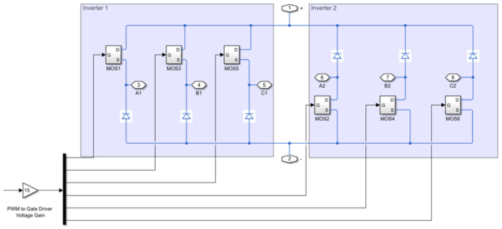
For more information about hardware connections for SRM, see Instructions for Switched Reluctance Motor (SRM) Setup.
Generate Code and Run Model on Target Hardware
1. Simulate the target model and observe the simulation results.
2. Connect the hardware.
3. The model computes the ADC (or current) offset values by default. To disable this functionality, update the value 0 to the variable inverter.ADCOffsetCalibEnable in the model initialization script.
Alternatively, you can compute the ADC offset values and update them manually in the model initialization script.
4. Open the target model. If you want to change the default hardware configuration settings for the model, see Model Configuration Parameters.
5. Load a sample program on CPU2 of the LAUNCHXL-F28379D board to ensure that CPU2 is not mistakenly configured to use the board peripherals intended for CPU1. For example, load the program that operates the CPU2 blue LED by using GPIO31 (c28379D_cpu2_blink.slx). For more information about the sample program or model, see the Task 2 - Create, Configure and Run the Model for TI Delfino F28379D LaunchPad (Dual Core) section in Getting Started with Texas Instruments C2000 Microcontroller Blockset (C2000 Microcontroller Blockset).
6. Use the Dwell Angle button to select one of the following options:
Online computation— Select this option to enable the online dwell angle computation algorithm and use the dwell angle computed in real-time for speed control of the SRM.
Constant angles— Select this option to disable the online dwell angle computation and use the variablesthetaONandthetaOFF(which define a fixed dwell angle) in the model initialization script for speed control of the SRM.
7. Click Build, Deploy & Start on the Hardware tab to deploy the target model to the hardware.
8. Check that the variables populated by the target model in the base workspace are correct.
9. Click the mcb_srm_spdctrl_host.slx host model hyperlink in the target model to open the associated host model.
For details about the serial communication between the host and target models, see Host-Target Communication.
10. In the model initialization script associated with the target model, specify the communication port using the variable target.comport. This variable updates the Port parameter of the Host Serial Setup, Host Serial Receive, and Host Serial Transmit blocks in the host model.
11. Update the reference speed value in the Reference Speed (RPM) field in the host model. It is recommended that you enter lower speeds during motor startup and gradually increase the speed later.
12. In the host model, select the debug signals that you want to monitor.
13. Run the host model by clicking Run on the Simulation tab.
14. After you connect the load to the motor shaft, change the position of the Motor switch to Start to start running the motor.
If the motor does not align or if it fails to start running in open-loop mode, increase the values of the start-up parameters listed in the Motor Start Up Parameters section of the model initialization script.
15. The example performs these procedures.
a. For constant angles:
Calibrate the quadrature encoder sensor (which includes alignment of the rotor with stator phase A).
Use the fixed dwell angle defined in the model initialization script to run SRM in closed loop according to Reference Speed (RPM).
b. For online computation:
Calibrate the quadrature encoder sensor (which includes alignment of the rotor with stator phase A).
Compute optimal dwell angle according to the load conditions and uses it to run SRM in closed loop according to Reference Speed (RPM).
16. Check the debug signals received from the target in the Scope in the host model.
References
[1] C. Mademlis and I. Kioskeridis, "Performance optimization in switched reluctance motor drives with online commutation angle control," in IEEE Transactions on Energy Conversion, vol. 18, no. 3, pp. 448-457, Sept. 2003, doi: 10.1109/TEC.2003.815854.