Pumping
In this section, you can find examples of pumping systems in multiple Simscape Fluids domains.
Featured Examples
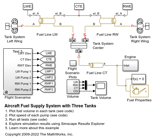
Aircraft Fuel Supply System with Three Tanks
Model an aircraft fuel supply system consisting of three tanks and an engine.
Aircraft Fuel Supply System with Three Tanks
Warning: This example uses the hydraulic domain, which will be removed in a future release. Find an equivalent example model that uses the isothermal liquid domain here: Aircraft Fuel Supply System with Three Tanks. To convert models to the isothermal liquid domain, use the hydraulicToIsothermalLiquid tool.
Closed-Loop Actuator with Variable-Displacement Pressure-Compensated Pump
Demonstrates closed-loop control of a hydraulic actuator position. The model uses a 4-way directional valve to control the position of a double-acting hydraulic actuator. The actuator acts against a load, which the model represents with blocks that model mass, viscous damping, Coulomb friction, constant force, and spring. The actuator is powered by a variable-displacement, pressure-compensated pump, which is driven by a motor. Pipe (IL) blocks model the pipelines between the valve, cylinder, pump, and tank.
Hydraulic Axial-Piston Motor
An axial piston motor with a test harness. To increase the fidelity of the simulation, this model uses a detailed representation of the motor that accounts for the interaction between the pistons, swash plate, and valve plate.
Hydraulic Axial-Piston Pump with Load-Sensing and Pressure-Limiting Control
A test rig designed to investigate the interaction between an axial-piston pump and a typical control unit simultaneously performing the load-sensing and pressure-limiting functions. To increase the fidelity of the simulation, this example uses a detailed model of the pump that accounts for the interaction between the pistons, swash plate, and valve plate.
Hydraulic Axial-Piston Pump with Load-Sensing and Pressure-Limiting Control
Warning: This example uses the hydraulic domain, which will be removed in a future release. Find an equivalent example model that uses the isothermal liquid domain here: Hydraulic Axial-Piston Pump with Load-Sensing and Pressure-Limiting Control. To convert models to the isothermal liquid domain, use the hydraulicToIsothermalLiquid tool.
Hydraulic Motor Driven by Load-Sensing Pump
A circuit that is equipped with a load-sensing velocity regulator installed between the pump and directional valve. Unlike a conventional meter-in velocity control, the load-sensing device automatically adjusts output pressure of the pump in such a way that it equals the sum of the preset pressure drop across the pressure-compensated flow control valve and the pressure induced by load. The pilot-operated pressure-relief valve in the Load-Sensing Velocity Control block is built of the Poppet Valve (IL) and the Pilot Valve Actuator (IL) blocks.
Hydraulic Motor Driven by Load-Sensing Variable-Displacement Pump
A circuit using a load-sensing and pressure-limiting unit in a conventional reciprocal system with variable load on the forward stroke. The unit limits output pressure to 300 bar and maintains a preset pressure drop in 10 bar across the velocity control orifice on the discharge port of the pump. The unit is built of two 3-way, 2-position valves, two single-acting valve actuators, and one double-acting valve actuator.
Lubrication System
A simplified version of a lubrication system fed with the centrifugal pump. The system consists of five major units: Pump Unit, Scavenge Unit, Heat Exchanger Manifold, Nozzle Manifold, and Control Unit. Both the pump and the scavenge unit are built around the centrifugal pump. The Scavenge Unit collects fluid discharged by nozzles and pumps it back into the reservoir of the Pump Unit. The Control Unit generates commands to bypass either the heat exchanger, represented as a local resistance, or the nozzles block. In a real system, these commands are generated by temperature sensors installed in lubrication cavities.
Lubrication System
Warning: This example uses the hydraulic domain, which will be removed in a future release. Find an equivalent example model that uses the isothermal liquid domain here: Lubrication System. To convert models to the isothermal liquid domain, use the hydraulicToIsothermalLiquid tool.
Priority Valve Controlling Two Hydraulic Motors
A pressure-compensated 3-way flow control valve. This valve maintains constant flow rate through the main hydraulic motor, which is connected to the pressure-compensated outlet of the flow control valve. It acts as a priority valve, diverting the excess flow to the auxiliary hydraulic motor if the main hydraulic motor receives enough fluid to maintain a preset angular velocity. The auxiliary motor is shut off completely if there is insufficient flow to power the main hydraulic motor.
Priority Valve Controlling Two Hydraulic Motors
Warning: This example uses the hydraulic domain, which will be removed in a future release. Find an equivalent example model that uses the isothermal liquid domain here: Priority Valve Controlling Two Hydraulic Motors. To convert models to the isothermal liquid domain, use the hydraulicToIsothermalLiquid tool.
Well with Jet Pump
A well jet pump installation. The well jet pump installation presented in this example consists of a surface-mounted centrifugal pump and a jet pump installed in the well below the surface of the water.
MATLAB Command
You clicked a link that corresponds to this MATLAB command:
Run the command by entering it in the MATLAB Command Window. Web browsers do not support MATLAB commands.
Website auswählen
Wählen Sie eine Website aus, um übersetzte Inhalte (sofern verfügbar) sowie lokale Veranstaltungen und Angebote anzuzeigen. Auf der Grundlage Ihres Standorts empfehlen wir Ihnen die folgende Auswahl: .
Sie können auch eine Website aus der folgenden Liste auswählen:
So erhalten Sie die bestmögliche Leistung auf der Website
Wählen Sie für die bestmögliche Website-Leistung die Website für China (auf Chinesisch oder Englisch). Andere landesspezifische Websites von MathWorks sind für Besuche von Ihrem Standort aus nicht optimiert.
Amerika
- América Latina (Español)
- Canada (English)
- United States (English)
Europa
- Belgium (English)
- Denmark (English)
- Deutschland (Deutsch)
- España (Español)
- Finland (English)
- France (Français)
- Ireland (English)
- Italia (Italiano)
- Luxembourg (English)
- Netherlands (English)
- Norway (English)
- Österreich (Deutsch)
- Portugal (English)
- Sweden (English)
- Switzerland
- United Kingdom (English)


