Water Supply System
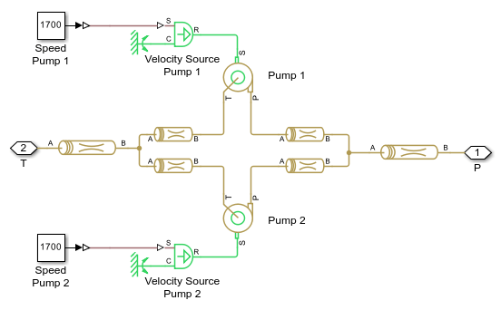
This example shows a water supply system consisting of three pumping stations located at 45, 25, and 30 m with respect to the reference plane, respectively. All three stations are expected to pump water in a tank located at 61 m. All tanks are large enough to assume that the fluid level remains nearly constant, allowing them to be modeled with the Reservoir (IL) block. The initial volume of water in each tank is set to 100  . Each pumping station consists of two centrifugal pumps installed in parallel with prime movers rotating at 1700 rpm. The pump characteristics are specified using lookup tables. All pipes are modeled using Pipe (IL) blocks.
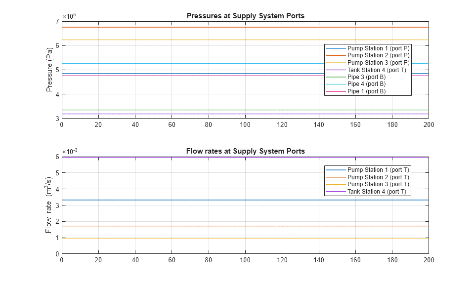
The objective of the simulation is to determine steady-state flow rates and pressures. No system dynamics are observed.
Model

Tank Station 1 Subsystem

Pump Station 1 Subsystem

Simulation Results from Simscape Logging
The plot below shows pressures and flow rates in the water supply system.
