Design Model by Using HDL Coder Native Floating Point and Intel Hard Floating Point
This example shows how to create a model design that uses both HDL Coder™ native floating-point (NFP) and Intel® hard floating-point (HFP) IP. Using the NFP and HFP blocks together in a mixed design offers better FPGA resource utilizations. For complex models, this mixed design allows you to have bigger design into the FPGA fabric.
Generate HDL Code for Model with NFP Library
1. Set the synthesis tool path by using the function hdlsetuptoolpath. For this example, use Intel Quartus Pro as your synthesis tool. To set up tools in your environment, run the hdlsetuptoolpath command using the synthesis tool path on your computer. For example, the function quartuspath returns the Intel Quartus Pro synthesis tool path.
hdlsetuptoolpath('ToolName', 'Intel Quartus Pro','ToolPath', quartuspropath);
Prepending following Intel Quartus Pro path(s) to the system path:
B:\share\apps\HDLTools\Altera\21.3-mw-0_pro\Windows\quartus\bin64
2. Open the Simulink® model hdlcoder_mixed_nfp_hfp. The model consists of a Tanh, Multiply, and Add block. The input data type is single.
open_system('hdlcoder_mixed_nfp_hfp.slx');
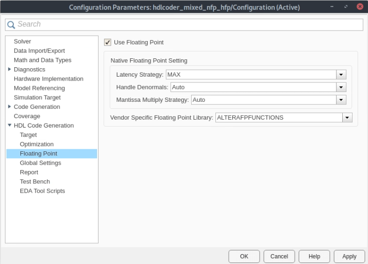
3. Open the Configuration Parameters dialog box. In the HDL Code Generation > Target pane, set Synthesis Tool to Intel Quartus Pro, set Family to Arria 10, and set Device to 10AS016C3U19E2LG.
4. In the Floating Point pane, select Use Floating Point to map the design to the native floating-point library. To map the design to a vendor-specific floating point library, set the Vendor Specific Floating Point Library to the library that aligns with your target hardware. In this example, the Vendor Specific Floating Point Library is set to ALTERAFPFUNCTIONS.
Click OK to save the changes.
5. To compile and simulate the generated code with QuestaSim, at the command line, set the Altera simulation library path by using the hdlsetup_param function. In this example, that path is saved in variable alterasimulationlibpath. For example, the simulation path can be C:\HDLTools\Altera\Questa_SimLibs\15.1\.
hdlset_param('hdlcoder_mixed_nfp_hfp', 'SimulationLibPath', alterasimulationlibpath);
6. Generate HDL code for the DUT subsystem, hdlcoder_mixed_nfp_hfp/DUT, by using the makehdl function.
makehdl('hdlcoder_mixed_nfp_hfp/DUT')### Generating HDL for 'hdlcoder_mixed_nfp_hfp/DUT'. ### Using the config set for model hdlcoder_mixed_nfp_hfp for HDL code generation parameters. ### Running HDL checks on the model 'hdlcoder_mixed_nfp_hfp'. ### Begin compilation of the model 'hdlcoder_mixed_nfp_hfp'... ### Working on the model 'hdlcoder_mixed_nfp_hfp'... ### 'AdaptivePipelining' is set to 'Off' for the model. 'AdaptivePipelining' can improve the achievable clock frequency and reduce the area usage on FPGA boards. To enable adaptive pipelining, please set the option to 'On'. When adaptive pipelining is enabled, it inserts pipeline registers to create patterns that efficiently map blocks to DSP units on the target FPGA device. ### 'LUTMapToRAM' is set to 'On' for the model. This option is used to map lookup tables to a block RAM in hardware. To disable pipeline insertion for mapping lookup tables to RAM, please set the option to 'Off'. ### Using B:\share\apps\HDLTools\Altera\21.3-mw-0_pro\Windows\quartus\bin64\..\sopc_builder\bin\ip-deploy for the selected floating point IP library. *************************************************************** Quartus is a registered trademark of Intel Corporation in the US and other countries. Portions of the Quartus Prime software code, and other portions of the code included in this download or on this DVD, are licensed to Intel Corporation and are the copyrighted property of third parties. For license details, refer to the End User License Agreement at http://fpgasoftware.intel.com/eula. *************************************************************** 2023.04.28.12:57:31 Info: alterafpf_add_single.alterafpf_add_single: B:/share/apps/hdltools/altera/21.3-mw-0_pro/windows/quartus/dspba/backend/windows64/cmdPolyEval -target Arria10 -frequency 100 -name none -noChanValid -enable -enableHardFP 1 -printMachineReadable -noFileGenerate -correctRounding FPAdd 8 23 2023.04.28.12:57:31 Info: alterafpf_add_single.alterafpf_add_single: B:/share/apps/hdltools/altera/21.3-mw-0_pro/windows/quartus/dspba/backend/windows64/cmdPolyEval -target Arria10 -frequency 100 -name none -noChanValid -enable -enableHardFP 1 -printMachineReadable -noFileGenerate -correctRounding FPAdd 8 23 2023.04.28.12:57:31 Info: Deploying alterafpf_add_single to C:\Users\clewis\OneDrive - MathWorks\Documents\MATLAB\ExampleManager\clewis.Bdoc23b.j2242084\hdlcoder-ex94013746\hdl_prj_mixed\hdlsrc\hdlcoder_mixed_nfp_hfp\Altera\Arria_10\10AS016C3U19E2LG\F100\alterafpf_add_single.ip ### Generating Altera(R) megafunction: alterafpf_add_single for target frequency of 100 MHz. ### alterafpf_add_single takes 3 cycles. ### Done. *************************************************************** Quartus is a registered trademark of Intel Corporation in the US and other countries. Portions of the Quartus Prime software code, and other portions of the code included in this download or on this DVD, are licensed to Intel Corporation and are the copyrighted property of third parties. For license details, refer to the End User License Agreement at http://fpgasoftware.intel.com/eula. *************************************************************** 2023.04.28.12:59:30 Info: alterafpf_mul_single.alterafpf_mul_single: B:/share/apps/hdltools/altera/21.3-mw-0_pro/windows/quartus/dspba/backend/windows64/cmdPolyEval -target Arria10 -frequency 100 -name none -noChanValid -enable -enableHardFP 1 -printMachineReadable -noFileGenerate -correctRounding FPMul 8 23 2023.04.28.12:59:30 Info: alterafpf_mul_single.alterafpf_mul_single: B:/share/apps/hdltools/altera/21.3-mw-0_pro/windows/quartus/dspba/backend/windows64/cmdPolyEval -target Arria10 -frequency 100 -name none -noChanValid -enable -enableHardFP 1 -printMachineReadable -noFileGenerate -correctRounding FPMul 8 23 2023.04.28.12:59:30 Info: Deploying alterafpf_mul_single to C:\Users\clewis\OneDrive - MathWorks\Documents\MATLAB\ExampleManager\clewis.Bdoc23b.j2242084\hdlcoder-ex94013746\hdl_prj_mixed\hdlsrc\hdlcoder_mixed_nfp_hfp\Altera\Arria_10\10AS016C3U19E2LG\F100\alterafpf_mul_single.ip ### Generating Altera(R) megafunction: alterafpf_mul_single for target frequency of 100 MHz. ### alterafpf_mul_single takes 3 cycles. ### Done. ### The code generation and optimization options you have chosen have introduced additional pipeline delays. ### The delay balancing feature has automatically inserted matching delays for compensation. ### The DUT requires an initial pipeline setup latency. Each output port experiences these additional delays. ### Output port 1: 49 cycles. ### Working on... GenerateModel ### Begin model generation 'gm_hdlcoder_mixed_nfp_hfp' .... ### Rendering DUT with optimization related changes (IO, Area, Pipelining)... ### Model generation complete. ### Begin VHDL Code Generation for 'hdlcoder_mixed_nfp_hfp'. ### Working on hdlcoder_mixed_nfp_hfp/DUT/nfp_tanh_single as hdl_prj_mixed\hdlsrc\hdlcoder_mixed_nfp_hfp\nfp_tanh_single.vhd. ### Working on hdlcoder_mixed_nfp_hfp/DUT as hdl_prj_mixed\hdlsrc\hdlcoder_mixed_nfp_hfp\DUT.vhd. ### Generating package file hdl_prj_mixed\hdlsrc\hdlcoder_mixed_nfp_hfp\DUT_pkg.vhd. ### Code Generation for 'hdlcoder_mixed_nfp_hfp' completed. ### Creating HDL Code Generation Check Report DUT_report.html ### HDL check for 'hdlcoder_mixed_nfp_hfp' complete with 0 errors, 0 warnings, and 2 messages. ### HDL code generation complete.
6. Generate the test bench for the Simulink model.
makehdltb('hdlcoder_mixed_nfp_hfp/DUT')### Begin TestBench generation. ### Generating HDL TestBench for 'hdlcoder_mixed_nfp_hfp/DUT'. ### Begin compilation of the model 'hdlcoder_mixed_nfp_hfp'... ### Begin compilation of the model 'gm_hdlcoder_mixed_nfp_hfp'... ### Begin simulation of the model 'gm_hdlcoder_mixed_nfp_hfp'... ### Collecting data... ### Generating test bench data file: hdl_prj_mixed\hdlsrc\hdlcoder_mixed_nfp_hfp\Out1_expected.dat. ### Working on DUT_tb as hdl_prj_mixed\hdlsrc\hdlcoder_mixed_nfp_hfp\DUT_tb.vhd. ### Generating package file hdl_prj_mixed\hdlsrc\hdlcoder_mixed_nfp_hfp\DUT_tb_pkg.vhd. ### HDL TestBench generation complete.
7. After makehdl runs,the HDL Code pane opens and displays the VHDL code for the components of the model. The generated DUT.vhd file shows the trigonometric function component tanh maps to a native floating-point component, and the Multiply and Add components map to hard floating-point components.

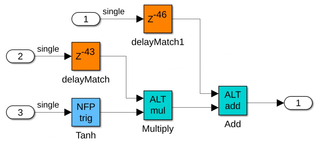
8. Open the generated model file gm_hdlcoder_mixed_nfp_hfp.slx. The blocks that map to native floating-point components are light blue and display NFP on the block mask. The blocks that map to the vendor-specific floating point components are cyan and have initials associated with the specified vendor library on the block mask. In this example, the blocks that map to vendor-specific floating point IP from the ALTERAFPFUNCTIONS library display the initials ALT. The Tanh block maps to a native floating-point component and the Multiply and Add blocks map to hard floating-point components.
HDL Coder adds matching delays to balance the added latency from the floating-point operator blocks. Double-click each floating-point block to see the latency added for each. For more information on latency with floating-point operators, see Latency Considerations with Native Floating Point.
9. The makehdl function generates the DUT_compile.do file that contains these commands to compile generated HDL files.
vlib workvmap -cvmap -c -modelsimini /mathworks/devel/src/commercial/HDLTools/Altera/Questa_SimLibs/18.1_20.2/modelsim.inivlib altera_fp_functions_1911vcom -work altera_fp_functions_1911 Altera/Arria_10/10AS016C3U19E2LG/F100/synth/alterafpf_add_single/altera_fp_functions_1911/dspba_library_package.vhdvcom -work altera_fp_functions_1911 Altera/Arria_10/10AS016C3U19E2LG/F100/synth/alterafpf_add_single/altera_fp_functions_1911/dspba_library.vhdvcom -work altera_fp_functions_1911 Altera/Arria_10/10AS016C3U19E2LG/F100/synth/alterafpf_add_single/altera_fp_functions_1911/alterafpf_add_single_altera_fp_functions_1911_y7txnay.vhdvcom -work altera_fp_functions_1911 Altera/Arria_10/10AS016C3U19E2LG/F100/synth/alterafpf_mul_single/altera_fp_functions_1911/alterafpf_mul_single_altera_fp_functions_1911_wfujeaa.vhdvlib workvcom DUT_pkg.vhdvcom Altera/Arria_10/10AS016C3U19E2LG/F100/synth/alterafpf_add_single.vhdvcom Altera/Arria_10/10AS016C3U19E2LG/F100/synth/alterafpf_mul_single.vhdvcom nfp_tanh_single.vhdvcom DUT.vhd
10. The makehdltb function generates the DUT_tb_compile.do file that contains these commands to compile generated HDL files.
vlib workvmap -cvmap -c -modelsimini /mathworks/devel/src/commercial/HDLTools/Altera/Questa_SimLibs/18.1_20.2/modelsim.inivlib altera_fp_functions_1911vcom -work altera_fp_functions_1911 Altera/Arria_10/10AS016C3U19E2LG/F100/synth/alterafpf_add_single/altera_fp_functions_1911/dspba_library_package.vhdvcom -work altera_fp_functions_1911 Altera/Arria_10/10AS016C3U19E2LG/F100/synth/alterafpf_add_single/altera_fp_functions_1911/dspba_library.vhdvcom -work altera_fp_functions_1911 Altera/Arria_10/10AS016C3U19E2LG/F100/synth/alterafpf_add_single/altera_fp_functions_1911/alterafpf_add_single_altera_fp_functions_1911_y7txnay.vhdvcom -work altera_fp_functions_1911 Altera/Arria_10/10AS016C3U19E2LG/F100/synth/alterafpf_mul_single/altera_fp_functions_1911/alterafpf_mul_single_altera_fp_functions_1911_wfujeaa.vhdvlib workvcom DUT_pkg.vhdvcom Altera/Arria_10/10AS016C3U19E2LG/F100/synth/alterafpf_add_single.vhdvcom Altera/Arria_10/10AS016C3U19E2LG/F100/synth/alterafpf_mul_single.vhdvcom nfp_tanh_single.vhdvcom DUT.vhdvcom DUT_tb_pkg.vhdvcom DUT_tb.vhd
11. The makehdltb function generates the DUT_tb_sim.do file that contains these commands for simulation when using the ModelSim® software.
onbreak resumeonerror resumevsim -t 1ps -L lpm -L altera_mf -voptargs=+acc work.DUT_tbadd wave sim:/DUT_tb/u_DUT/clkadd wave sim:/DUT_tb/u_DUT/resetadd wave sim:/DUT_tb/u_DUT/clk_enableadd wave sim:/DUT_tb/u_DUT/In1add wave sim:/DUT_tb/u_DUT/In2add wave sim:/DUT_tb/u_DUT/In3add wave sim:/DUT_tb/u_DUT/ce_outadd wave sim:/DUT_tb/u_DUT/Out1add wave sim:/DUT_tb/Out1_refrun -all
Verify Functionality by Using ModelSim Simulation
Open ModelSim and navigate to the folder containing the DO files.
Run the DO files in this order:
do DUT_compile.do
do DUT_tb_compile.do
do DUT_tb_sim.do
This figure shows the ModelSim simulation with the a message at the end of the log to indicate that the tests passed.

Design Synthesis in Intel Quartus Pro
To perform design synthesis of the mixed NFP and HFP design in Intel Quartus Pro software, follow these steps:
1. Open Intel Quartus Pro and create a project.
2. Add the generated HDL files to the Quartus project, including the top module DUT and the other supporting files.
3. Set DUT as top module in the Quartus project.
4. Perform design synthesis by following the Intel Quartus Pro workflow.
See Also
hdlcoder.FloatingPointTargetConfig | createFloatingPointTargetConfig | hdlcoder.FloatingPointTargetConfig.IPConfig | customize