Modeling with Simulink, Stateflow, and MATLAB Function Blocks
You can follow this guideline as a general practice for modeling your design with various blocks in the Simulink® Library Browser.
Each guideline has a severity level that indicates the level of compliance requirements. To learn more, see HDL Modeling Guidelines Severity Levels.
Guideline ID
1.1.8
Severity
Informative
Description
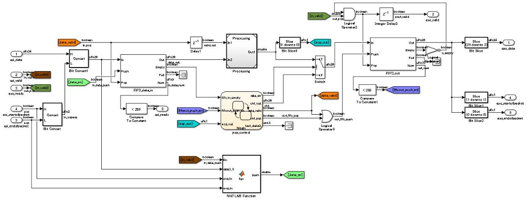
When you create a Simulink model for HDL code generation, use Simulink blocks, MATLAB Function blocks, and Stateflow® blocks based on the application. This figure shows an example of how you can use the various blocks inside your DUT.
Simulink Blocks
Use Simulink blocks to model arithmetic algorithms that perform numerical processing or contains feedback loops.
MATLAB Function Blocks
Use MATLAB Function blocks to model the control logic, conditional branches such as if-else statements, and simple state machines. You can also use MATLAB Function blocks to model an IP that is written using MATLAB® code.
Stateflow Blocks
Use these Stateflow blocks to model your algorithm:
State Transition Table (Stateflow): Use these blocks to model state machines that control the output using knowledge of the past and the present.
Chart (Stateflow): Use these blocks to model flow charts using conditional if-else branches and state machines that control the output using knowledge of the past and the present.
Truth Table (Stateflow): Use these blocks to model conditional if-else branches.
You can model combinational logic using Stateflow blocks. For more complex operations and operations that change timing such as pipeline insertion and processing, use Simulink blocks. You can then use the Stateflow logic to process the result calculated from the Simulink blocks
Model References
For significantly large algorithms that have complex computations, you can partition the design into a hierarchy of smaller designs. Use this partitioning for reuse, modular development, and accelerated simulation. You can reuse models by including them as Model blocks inside a top model. The model that reuses this block is called the top model and the block that is reused or included in the top model is called the referenced model.
Note
When you generate HDL code for a Subsystem that is not at the top level of the model, HDL Coder™ converts the Subsystem to a model reference.
A referenced model is treated similar to an Atomic Subsystem. In some cases, an algebraic loop can potentially occur, and can prevent HDL code generation. To generate code, either remove the algebraic loop in your design, or, in the Configuration Parameters dialog box, specify the Minimize algebraic loop occurrences setting.
BlackBox Subsystems
For subsystems that you want to simulate in your design and to include the HDL
code that you authored, use BlackBox subsystems. To create a
BlackBox Subsystem, set the HDL Architecture of a
Subsystem or Model reference to BlackBox.
You can use this architecture to incorporate handwritten HDL code into a
Simulink model. For more information, see Verify the Combination of Hand-Written and Generated HDL Code (HDL Verifier).
If you generate a Simulink model using the HDL code that you authored, use HDL import. To learn more, see Import HDL Code and Generate Simulink Model.
HDL Cosimulation Blocks
If you have a HDL simulator such as Siemens® ModelSim™ or Cadence Incisive®, you can use HDL Cosimulation (HDL Verifier) blocks to simulate the HDL code for the DUT and instantiate this HDL code in the generated code.