Scenario Reader
Read driving scenario into model
Libraries:
Automated Driving Toolbox /
Driving Scenario and Sensor Modeling
Description
The Scenario Reader block reads the roads and actors from a scenario file
created using the Driving Scenario
Designer app or from a drivingScenario object. The block outputs the
poses of actors in either the coordinate system of the ego vehicle or the world coordinates of
the scenario. You can also output the lane boundaries or output the ego vehicle pose for use
in the 3D simulation environment. The block also allows output of the ego vehicle state, which
includes acceleration measurements, for use with sensor models.
To generate object and lane boundary detections from output actor poses and lane boundaries, pass the pose and boundary outputs to sensor blocks. Use the synthetic detections generated from these sensors to test the performance of sensor fusion algorithms, tracking algorithms, and other automated driving assistance system (ADAS) algorithms. To visualize the performance of these algorithms, use the Bird's-Eye Scope.
You can read the ego vehicle from the scenario or specify an ego vehicle defined in your model as an input to the Scenario Reader block. Use this option to test closed-loop vehicle controller algorithms, such as autonomous emergency braking (AEB), lane keeping assist (LKA), or adaptive cruise control (ACC).
Examples
Test Open-Loop ADAS Algorithm Using Driving Scenario
Test open-loop ADAS algorithms in Simulink® by using driving scenarios saved from the Driving Scenario Designer app.

Test Closed-Loop ADAS Algorithm Using Driving Scenario
Test closed-loop ADAS algorithms in Simulink by using driving scenarios saved from the Driving Scenario Designer app.
Generate Sensor Blocks Using Driving Scenario Designer
Generate Simulink blocks for a driving scenario and sensors that were built using the Driving Scenario Designer app.

Visualize Sensor Data from Unreal Engine Simulation Environment
Visualize sensor coverage areas and detections obtained from high-fidelity radar and lidar sensors in the Unreal Engine® simulation environment.
Limitations
The Scenario Reader block does not read sensor data from scenario files saved from the Driving Scenario Designer app and sensors added to the driving scenario object using the
addSensorsobject function. To reproduce sensors in Simulink, in the app, open the scenario file that contains the sensors. Then, from the app toolstrip, select Export > Export Sensor Simulink Model. Copy the generated sensor blocks into an existing model. Alternatively, select Export > Export Simulink Model and start a new model from the generated Scenario Reader block and sensor blocks.Large road networks, including ASAM OpenDRIVE® road networks, can take up to several minutes to read into models.
Ports
Input
Output
Scenario actor poses, returned as a Simulink bus containing a MATLAB structure.
The structure has these fields.
| Field | Description | Type |
|---|---|---|
NumActors | Number of actors | Nonnegative integer |
Time | Current simulation time | Real-valued scalar |
Actors | Actor poses | NumActors-length array of actor pose structures |
Each actor pose structure in Actors has these fields.
| Field | Description |
|---|---|
ActorID | Scenario-defined actor identifier, specified as a positive integer. |
Position | Position of actor, specified as a real-valued vector of the form [x y z]. Units are in meters. |
Velocity | Velocity (v) of actor in the x- y-, and z-directions, specified as a real-valued vector of the form [vx vy vz]. Units are in meters per second. |
Roll | Roll angle of actor, specified as a real-valued scalar. Units are in degrees. |
Pitch | Pitch angle of actor, specified as a real-valued scalar. Units are in degrees. |
Yaw | Yaw angle of actor, specified as a real-valued scalar. Units are in degrees. |
AngularVelocity | Angular velocity (ω) of actor in the x-, y-, and z-directions, specified as a real-valued vector of the form [ωx ωy ωz]. Units are in degrees per second. |
The pose of the ego vehicle is excluded from the Actors
array.
To return actor poses from the block, you must run the entire driving scenario simulation to completion.
Scenario lane boundaries, returned as a Simulink bus containing a MATLAB structure.
The structure has these fields.
| Field | Description | Type |
|---|---|---|
NumLaneBoundaries | Number of lane boundaries | Nonnegative integer |
Time | Current simulation time | Real scalar |
LaneBoundaries | Lane boundaries starting from the leftmost lane with respect to the ego vehicle. | NumLaneBoundaries-length array of lane boundary structures |
Each lane boundary structure in LaneBoundaries has these
fields.
| Field | Description |
| Lane boundary coordinates, specified as a real-valued N-by-3 matrix, where N is the number of lane boundary coordinates. Lane boundary coordinates define the position of points on the boundary at specified longitudinal distances away from the ego vehicle, along the center of the road.
This matrix also includes the boundary coordinates at zero distance from the ego vehicle. These coordinates are to the left and right of the ego-vehicle origin, which is located under the center of the rear axle. Units are in meters. |
| Lane boundary curvature at each row of the Coordinates matrix, specified
as a real-valued N-by-1 vector. N is the
number of lane boundary coordinates. Units are in radians per meter. |
| Derivative of lane boundary curvature at each row of the Coordinates
matrix, specified as a real-valued N-by-1 vector.
N is the number of lane boundary coordinates. Units are
in radians per square meter. |
| Initial lane boundary heading angle, specified as a real scalar. The heading angle of the lane boundary is relative to the ego vehicle heading. Units are in degrees. |
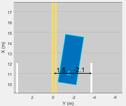
| Lateral offset of the ego vehicle position from the lane boundary, specified as a real scalar. An offset to a lane boundary to the left of the ego vehicle is positive. An offset to the right of the ego vehicle is negative. Units are in meters. In this image, the ego vehicle is offset 1.5 meters from the left lane and 2.1 meters from the right lane.
|
| Type of lane boundary marking, specified as one of these values:
|
| Saturation strength of the lane boundary marking, specified as a real scalar from 0 to
1. A value of |
| Lane boundary width, specified as a positive real scalar. In a double-line lane marker, the same width is used for both lines and for the space between lines. Units are in meters. |
| Length of dash in dashed lines, specified as a positive real scalar. In a double-line lane marker, the same length is used for both lines. |
| Length of space between dashes in dashed lines, specified as a positive real scalar. In a dashed double-line lane marker, the same space is used for both lines. |
The number of returned lane boundary structures depends on the Lane boundaries to output parameter value.
Dependencies
To enable this port, set these parameters in this order:
Set the Coordinate system of actors output parameter to
Vehicle coordinates.Set the Lane boundaries to output parameter to
Ego lane boundariesorAll lane boundaries.
Ego vehicle pose, returned as a Simulink bus containing a MATLAB structure.
The structure must contain these fields.
| Field | Description |
|---|---|
ActorID | Scenario-defined actor identifier, specified as a positive integer. |
Position | Position of actor, specified as a real-valued vector of the form [x y z]. Units are in meters. |
Velocity | Velocity (v) of actor in the x- y-, and z-directions, specified as a real-valued vector of the form [vx vy vz]. Units are in meters per second. |
Roll | Roll angle of actor, specified as a real-valued scalar. Units are in degrees. |
Pitch | Pitch angle of actor, specified as a real-valued scalar. Units are in degrees. |
Yaw | Yaw angle of actor, specified as a real-valued scalar. Units are in degrees. |
AngularVelocity | Angular velocity (ω) of actor in the x-, y-, and z-directions, specified as a real-valued vector of the form [ωx ωy ωz]. Units are in degrees per second. |
Dependencies
To enable this port, set these parameters in this order:
Set the Coordinate system of actors output parameter to
Vehicle coordinates.Set the Source of ego vehicle parameter to
Scenario.Select the Output ego vehicle pose parameter.
Ego vehicle state, returned as a Simulink bus containing a MATLAB structure.
The structure must contain these fields.
| Field | Description |
|---|---|
Position | Position of actor, specified as a real-valued vector of the form [x y z]. Units are in meters. |
Velocity | Velocity (v) of actor in the x- y-, and z-directions, specified as a real-valued vector of the form [vx vy vz]. Units are in meters per second. |
Orientation | Orientation of actor, specified as a real-valued vector of
[ |
AngularVelocity | Angular velocity (ω) of actor in the x-, y-, and z-directions, specified as a real-valued vector of the form [ωx ωy ωz]. Units are in degrees per second. |
Acceleration | Acceleration (a) of actor in the x- y-, and z-directions, specified as a real-valued vector of the form [ax ay az]. Units are in meters per second squared. |
Dependencies
To enable this port, set these parameters in this order:
Set the Coordinate system of actors output parameter to
Vehicle coordinates.Set the Source of ego vehicle parameter to
Scenario.Select the Output ego vehicle state parameter.
Parameters
Scenario
Source of driving scenario, specified as one of these options:
From file— In the Driving Scenario Designer file name parameter, specify the name of a scenario file that was saved from the Driving Scenario Designer app.From workspace— In the MATLAB or model workspace variable name parameter, specify the name of a MATLAB or model workspace variable that contains adrivingScenarioobject.
Scenario file name, specified as a scenario file on the MATLAB search path or as the full path to a scenario file. A scenario file must
be a MAT-file saved from the Driving Scenario
Designer app. If the Source of ego vehicle parameter is set
to Scenario, then the scenario must contain an ego vehicle.
Otherwise, the block returns an error during simulation.
If the specified scenario file contains sensors, the block ignores them. To include sensors from the scenario in your model, see Tips.
The default scenario file shows an ego vehicle traveling north on a straight, two-lane road, with another vehicle traveling south in the opposite lane.
To add a scenario file to the MATLAB search path, use the addpath function. For example, this code adds the set of folders
containing prebuilt Euro NCAP® scenarios to the MATLAB search path.
path = fullfile(matlabroot,'toolbox','shared','drivingscenario', ... 'PrebuiltScenarios','EuroNCAP'); addpath(genpath(path))
In the Driving Scenario Designer file name parameter, you can
then specify the name of any scenario located in these folders, without having to
specify the full file path. For example:
AEB_PedestrianChild_Nearside_50width.mat.
When you are done using the scenario in your models, you can remove any added
folders from the MATLAB search path by using the rmpath function.
rmpath(genpath(path))
Dependencies
To enable this parameter, set the Source of driving scenario
parameter to From file.
Scenario variable name, specified as the name of a MATLAB or model workspace variable that contains a valid drivingScenario object. If a scenario variable with the same name appears in
both the MATLAB and model workspace, the block uses the variable defined in the model
workspace.
If the Source of ego vehicle parameter is set to
Scenario, then the drivingScenario object
must contain an ego vehicle. To designate which actor in the object is the ego vehicle,
in the Ego vehicle ActorID parameter, specify the
ActorID property value of that actor.
The default variable name, scenario, is the default name of
drivingScenario objects produced by the MATLAB functions that are exported from the Driving Scenario
Designer app. By default, this variable is not included in the MATLAB or model workspace.
Dependencies
To enable this parameter, set the Source of driving scenario
parameter to From workspace.
Coordinate system of the output actors, specified as one of these values:
Vehicle coordinates— Coordinates are defined with respect to the ego vehicle. Select this value when your scenario has only one ego vehicle.World coordinates— Coordinates are defined with respect to the driving scenario. Select this value in multi-agent scenarios that contain more than one ego vehicle. If you select this value, model visualization using the Bird's-Eye Scope is not supported.
For more details on the vehicle and world coordinate systems, see Coordinate Systems in Automated Driving Toolbox.
Source of ego vehicle, specified as one of these options:
Scenario— Use the ego vehicle defined in the scenario that is specified by the Driving Scenario Designer file name or MATLAB or model workspace variable name parameter. The pose of the ego vehicle is excluded from the Actors output port. Actor positions are in vehicle coordinates, meaning that they are relative to the world coordinate position of the ego vehicle in the scenario.Select this option to test open-loop ADAS algorithms, where the ego vehicle behavior is predefined and does not change as the scenario advances. For an example, see Test Open-Loop ADAS Algorithm Using Driving Scenario.
Input port— Specify the ego vehicle by using the Ego Vehicle input port. The pose of the ego vehicle is not included in the Actors output port.With this option, the ego vehicle in your model must include a starting position that is in world coordinates. All other actor poses are in vehicle coordinates and are positioned relative to the ego vehicle. For an example of an ego vehicle with defined position information, see Lane Keeping Assist with Lane Detection. When defining the starting position of the ego vehicle, consider using the position that is already defined in the scenario. By using this position, if you set Source of ego vehicle to
Scenarioand then back toInput port, you do not have to manually change the starting position.Select this option to test closed-loop ADAS algorithms, where the ego vehicle reacts to changes as the scenario advances. For an example, see Test Closed-Loop ADAS Algorithm Using Driving Scenario.
Dependencies
To enable this parameter, set the Coordinate system of actors
output parameter to Vehicle
coordinates.
Actor ID of ego vehicle, specified as a positive integer. Use this parameter to
simulate using the ego vehicle that is read from a drivingScenario
object.
When Source of ego vehicle is set to
Scenario, set this parameter to anActorIDvalue that is stored in theActorsproperty of the specifieddrivingScenarioobject. To check validActorIDvalues, use this syntax, wherescenariois the name of thedrivingScenariovariable name.actorIDs = [scenario.Actors.ActorID]
When Source of ego vehicle is set to
Input Port, you must set this parameter to theActorIDvalue at the Ego Vehicle input port of the block.
Dependencies
To enable this parameter, set these parameters in this order:
Set the Source of driving scenario parameter to
From workspace.Set the Coordinate system of actors output parameter to
Vehicle coordinates.
Select this parameter to output the pose of the ego vehicle at the Ego Vehicle Pose port.
Dependencies
To enable this parameter, set the Coordinate system of actors
output parameter to Vehicle coordinates and
the Source of ego vehicle parameter to
Scenario.
Select this parameter to output the state of the ego vehicle at the Ego Vehicle State port.
Dependencies
To enable this parameter, set the Coordinate system of actors
output parameter to Vehicle coordinates and
the Source of ego vehicle parameter to
Scenario.
To output ego vehicle state, you must create the trajectory of the ego vehicle
using the smoothTrajectory function in the driving scenario API or by selecting
Use smooth, jerk-limited trajectory parameter in the Driving Scenario
Designer app.
Select this parameter to orient the ego vehicle to follow the elevation of the road surface. The block updates the elevation, roll, pitch, and yaw of the ego vehicle and outputs actors and lane boundaries relative to the updated ego vehicle coordinates. The block does not update the velocity or angular velocity of the ego vehicle.
Use this parameter in closed-loop simulations where the elevation of the road network varies.
Note
At the junctions of roads that have different elevations and banking angles, the updated ego vehicle values might not be accurate.
In open-loop simulations, where Source of ego vehicle is set to
Scenario, the ego vehicle follows the elevation specified
in the driving scenario.
Dependencies
To enable this parameter, set Coordinate system of actors
output to Vehicle coordinates and
Source of ego vehicle to Input
port.
Sample time of simulation, in seconds, specified as a positive real scalar.
Inherited and continuous sample times are not supported. This sample time is separate
from the sample times that the Driving Scenario Designer app and
drivingScenario object use during simulation.
Lanes
Lane boundaries to output, specified as one of these options:
None— Do not output any lane boundaries.Ego vehicle lane boundaries— Output the left and right lane boundaries of the ego vehicle.All lane boundaries— Output all lane boundaries of the road on which the ego vehicle is traveling.
If you select Ego vehicle lane boundaries or
All lane boundaries, then the block returns the lane
boundaries in the Lane Boundaries output port.
Dependencies
To enable this parameter, set the Coordinate system of actors
output parameter to Vehicle
coordinates.
Distances from the ego vehicle at which to compute the lane boundaries, specified as an N-element real-valued vector. N is the number of distance values. When detecting lanes from rear-facing cameras, specify negative distances. When detecting lanes from front-facing cameras, specify positive distances. Units are in meters.
By default, the block computes 101 lane boundaries over the range from 150 meters behind the ego vehicle to 150 meters ahead of the ego vehicle. These distances are linearly spaced 3 meters apart.
Example: 1:0.1:10 computes a lane boundary every 0.1 meters over
the range from 1 to 10 meters ahead of the ego vehicle.
Dependencies
To enable this parameter, set the Lane boundaries to output
parameter to Ego vehicle lane boundaries or
All lane boundaries.
Lane boundary location on the lane markings, specified as one of the options in this table.
| Lane Boundary Location | Description | Example |
|---|---|---|
Center of lane markings | Lane boundaries are centered on the lane markings. | A three-lane road has four lane boundaries: one per lane marking.
|
Inner edge of lane markings | Lane boundaries are placed at the inner edges of the lane markings. | A three-lane road has six lane boundaries: two per lane.
|


Dependencies
To enable this parameter, set the Lane boundaries to output
parameter to Ego vehicle lane boundaries or
All lane boundaries.
Port Settings
Source of the name for the actor poses bus returned in the Actors output port, specified as one of these options:
Auto— The block automatically creates an actor poses bus name.Property— Specify the actor poses bus name by using the Actors bus name parameter.
Name of the actor poses bus returned in the Actors output port, specified as a valid bus name.
The custom actor poses bus you specify must match the structure defined by the
Actors output port. To create a custom actor bus, use the
Simulink.Bus.createObject function, specifying the structure
from the Actors output port as the input argument.
Dependencies
To enable this parameter, set Source of actors bus name to Property.
Source of the maximum number of actors that you can have in the driving scenario, specified as one of these options:
Scenario— The block sets the maximum number of actors to the number of actors in the driving scenario. This value is equal to theNumActorsfield of the bus returned by the Actors output port. When you change the input scenario, the maximum number of actors updates to match the newNumActorsvalue.Property— Specify the maximum number of actors by using the Maximum number of actors parameter. Select this option when you want to reuse the same actor bus across scenarios that have varying numbers of actors, such as when outputting actors from a referenced model.
Maximum number of actors that you can have in the scenario, specified as a positive integer.
Dependencies
To enable this parameter, set the Source of maximum number of
actors parameter to Property.
Source of the name for the lane boundaries bus returned in the Lane Boundaries output port, specified as one of these options:
Auto— The block automatically creates a lane boundaries bus name.Property— Specify the lane boundaries bus name by using the Lane boundaries bus name parameter.
Dependencies
To enable this parameter:
Set the Coordinate system of actors output parameter to
Vehicle coordinates.Set the Lane boundaries to output parameter to
Ego vehicle lane boundariesorAll lane boundaries.
Name of the lane boundaries bus returned in the Lane Boundaries output port, specified as a valid bus name.
Dependencies
To enable this parameter:
Set the Coordinate system of actors output parameter to
Vehicle coordinates.Set the Lane boundaries to output parameter to
Ego vehicle lane boundariesorAll lane boundaries.Set the Source of lane boundaries bus name parameter to
Property.
Source of the maximum number of lane boundaries that you can have in the driving scenario, specified as one of these options:
Scenario— The block sets the maximum number of lane boundaries to the number of lane boundaries in the driving scenario. This value is equal to theNumLaneBoundariesfield of the bus returned by the Lane Boundaries output port. When you change the input scenario, the maximum number of lane boundaries updates to match the newNumLaneBoundariesvalue.Property— Specify the maximum number of lane boundaries by using the Maximum number of lane boundaries parameter. Select this option when you want to reuse the same lane boundaries bus across scenarios that have varying numbers of lane boundaries, such as when outputting lane boundaries from a referenced model.
Dependencies
To enable this parameter:
Set the Coordinate system of actors output parameter to
Vehicle coordinates.Set the Lane boundaries to output parameter to
All
                      lane boundaries
.
Maximum number of lane boundaries that you can have in the scenario, specified as a positive integer.
Dependencies
To enable this parameter:
Set the Coordinate system of actors output parameter to
Vehicle coordinates.Set the Lane boundaries to output parameter to
All lane boundaries.Set the Source of maximum number of lane boundaries parameter to
Property.
Source of the name for the ego vehicle pose bus returned in the Ego Vehicle Pose output port, specified as one of these options:
Auto— The block automatically creates an ego vehicle pose bus name.Property— Specify the ego vehicle pose bus name by using the Ego vehicle pose bus name parameter.
Dependencies
To enable this parameter, select the Output ego vehicle pose parameter.
Name of the ego vehicle pose bus returned in the Ego Vehicle Pose output port, specified as a valid bus name.
Dependencies
To enable this parameter, select the Output ego vehicle pose
parameter and set the Source of ego vehicle pose bus name
parameter to Property.
Source of the name for the ego vehicle state bus returned in the Ego Vehicle State output port, specified as one of these options:
Auto— The block automatically creates an ego vehicle state bus name.Property— Specify the ego vehicle state bus name by using the Ego vehicle state bus name parameter.
Dependencies
To enable this parameter, select the Output ego vehicle state parameter.
Name of the ego vehicle state bus returned in the Ego Vehicle State output port, specified as a valid bus name.
Dependencies
To enable this parameter, select the Output ego vehicle state
parameter and set the Source of ego vehicle state bus name
parameter to Property.
Select this parameter to display the coordinate system of block inputs and outputs on the Scenario Reader block in the block diagram.
The Ego Vehicle input and output are always in world coordinates.
The Lane Boundaries output is always in vehicle coordinates.
You can return the Actors output in either vehicle or world coordinates, depending on the Coordinate system of actors output parameter selection.
Simulation
Tips
For best results, use only one active Scenario Reader block per model. To use multiple Scenario Reader blocks in one model, switch between the blocks by specifying them in a variant subsystem.
To test your algorithm on variations of a driving scenario, you can update the scenario between simulations.
If the source of the scenario is a scenario file, open the scenario file in the Driving Scenario Designer app, update the parameters, and resave the file.
If the source of the scenario is a
drivingScenarioobject, update the object in the MATLAB or model workspace. Alternatively, import the object into the app, modify the scenario in the app, and then generate a new object from the app.
To switch between scenarios with different parameter settings, you can use Simulink Test™ software. For an example, see Automate Testing for Highway Lane Following.
Extended Capabilities
Version History
Introduced in R2019a