estimateMonoCameraParameters
Estimate extrinsic monocular camera parameters using calibration pattern
Syntax
Description
[
estimates the extrinsic parameters of a monocular camera by using the intrinsic parameters
of the camera and a calibration pattern. The returned extrinsic parameters define the yaw,
pitch, and roll rotation angles between the camera
coordinate system and vehicle coordinate system
axes. The function also returns the height of the camera above the ground. Specify the
intrinsic parameters, the image and world coordinates of the calibration pattern key points,
and the height of the calibration pattern's origin above the ground. The calibration pattern
can be a checkerboard or a circle grid pattern.pitch,yaw,roll,height] = estimateMonoCameraParameters(intrinsics,imagePoints,worldPoints,patternOriginHeight)
By default, the function assumes that the camera is facing forward and that the calibration pattern is parallel with the ground. For all possible camera and calibration pattern placements, see Calibrate a Monocular Camera.
[
specifies options using one or more name-value pairs, in addition to the inputs and outputs
from the previous syntax. For example, you can specify the orientation or position of the
calibration pattern.pitch,yaw,roll,height] = estimateMonoCameraParameters(___,Name,Value)
Examples
Configure a monocular fisheye camera by removing lens distortion and then estimating the camera's extrinsic parameters. Use an image of a checkerboard as the calibration pattern. For a more detailed look at how to configure a monocular camera that has a fisheye lens, see the Configure Monocular Fisheye Camera example.
Load the intrinsic parameters of a monocular camera that has a fisheye lens. intrinsics is a fisheyeIntrinsics object.
ld = load("fisheyeCameraIntrinsics");
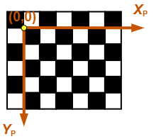
intrinsics = ld.intrinsics;Load an image of a checkerboard pattern that is placed flat on the ground. This image is for illustrative purposes and was not taken from a camera mounted to the vehicle. In a camera mounted to the vehicle, the X-axis of the pattern points to the right of the vehicle, and the Y-axis of the pattern points to the camera. Display the image.
I = imread("checkerboard.png");
imshow(I)
Detect the coordinates of the checkerboard corners in the image.
[imagePoints,patternDims] = detectCheckerboardPoints(I);
Generate the corresponding world coordinates of the corners.
squareSize = 0.029; % Square size in meters
worldPoints = patternWorldPoints("checkerboard",patternDims,squareSize);
Estimate the extrinsic parameters required to configure the monoCamera object. Because the checkerboard pattern is directly on the ground, set the height of the pattern's origin to 0.
patternOriginHeight = 0;
[pitch,yaw,roll,height] = estimateMonoCameraParameters(intrinsics, ...
                             imagePoints,worldPoints,patternOriginHeight);
Because monoCamera does not accept fisheyeIntrinsics objects, remove distortion from the image and compute new intrinsic parameters from the undistorted image. camIntrinsics is an cameraIntrinsics object. Display the image to confirm distortion is removed.
[undistortedI,camIntrinsics] = undistortFisheyeImage(I,intrinsics,Output="full");
imshow(undistortedI)
Configure the monocular camera using the estimated parameters.
monoCam = monoCamera(camIntrinsics,height,Pitch=pitch,Yaw=yaw,Roll=roll)
monoCam =
  monoCamera with properties:

        Intrinsics: [1×1 cameraIntrinsics]
        WorldUnits: 'meters'
            Height: 0.4447
             Pitch: 21.8459
               Yaw: -3.6130
              Roll: -3.1707
    SensorLocation: [0 0]
Configure a monocular camera using a circle grid pattern and then estimate the camera's extrinsic parameters. Use an image of an asymmetric circle grid as the calibration pattern.
Load the intrinsic parameters of a monocular camera. intrinsics is a cameraIntrinsics object.
ld = load("IRCameraIntrinsics");
intrinsics = ld.intrinsics;
Load an image of an asymmetric circle grid pattern that is placed parallel to the ground placed at a height. This image is for illustrative purposes and was not taken from a camera mounted to the vehicle. In a camera mounted to the vehicle, the X-axis of the pattern points to the right of the vehicle, and the Y-axis of the pattern points to the camera. Display the image.
imageFileName = fullfile(toolboxdir("vision"),"visiondata", ...
    "calibration","circleGrid","stereo","left","left07.jpg");
I = imread(imageFileName);
imshow(I)

Define the circle grid pattern dimensions and detect the centers of the circles in the image.
patternDims = [4 11];
imagePoints = detectCircleGridPoints(I,patternDims);
Generate the corresponding world coordinates of the corners.
centerDistance = 0.0365; % meters
worldPoints = patternWorldPoints("circle-grid-asymmetric",patternDims,centerDistance);
Estimate the extrinsic parameters required to configure the monoCamera object. Because the checkerboard pattern is placed at a height of 1.2 m from the ground, set the height of the pattern's origin to 1.2 m.
patternOriginHeight = 1.2; % meters
[pitch,yaw,roll,height] = estimateMonoCameraParameters(intrinsics, ...
                             imagePoints,worldPoints,patternOriginHeight);
Configure the monocular camera using the estimated parameters.
monoCam = monoCamera(intrinsics,height,Pitch=pitch,Yaw=yaw,Roll=roll)
monoCam =
  monoCamera with properties:

        Intrinsics: [1×1 cameraIntrinsics]
        WorldUnits: 'meters'
            Height: 1.3869
             Pitch: 60.2886
               Yaw: -26.5963
              Roll: -45.7440
    SensorLocation: [0 0]
Define the area in front of the camera that you want to transform into a bird's-eye view. Set an area from 0 to 2.5 meters in front of the camera, with 1.75 meters to either side of the camera.
bottomOffset = 0; % meters
distAhead = 2.5; % meters
spaceToOneSide = 1.75; % meters

outView = [bottomOffset,distAhead,-spaceToOneSide,spaceToOneSide];
Set the output image width to 250 pixels. Compute the output length automatically from the width by setting the length to NaN.
outImageSize = [NaN,250];
Create an object for performing bird's-eye-view transforms, using the previously defined parameters.
birdsEye = birdsEyeView(monoCam,outView,outImageSize);
Transform the input image into a bird's-eye-view image and display the result.
BEV = transformImage(birdsEye,I);
imshow(BEV)

Input Arguments
Intrinsic camera parameters, specified as a cameraIntrinsics, fisheyeIntrinsics, or a cameraIntrinsicsKB object.
Calibration pattern images produced by these cameras can include lens distortion, which can affect the accuracy of corner point detections. To remove lens distortion and compute new intrinsic parameters, use these functions:
For
cameraIntrinsicsorcameraIntrinsicskbobjects, useundistortImage.For
fisheyeIntrinsicsobjects, useundistortFisheyeImage.
Image coordinates of calibration pattern key points, specified as an
M-by-2 matrix of M number of
[x
y] vectors. These points must come from an image captured by a
monocular camera. To detect these points in an image, use the detectCheckerboardPoints function.
estimateMonoCameraParameters assumes that all points in
worldPoints are in the
(XP,
YP) plane and that M is
greater than or equal to 4. To specify the height of the
(XP,
YP) plane above the ground, use
patternOriginHeight.
Data Types: single | double
World coordinates of the key points in the calibration pattern, specified as an M-by-2 matrix of M number of [x y] vectors.
estimateMonoCameraParameters assumes that all points in
worldPoints are in the
(XP,
YP) plane and that M is
greater than or equal to 4. To specify the height of the
(XP,
YP) plane above the ground, use
patternOriginHeight.
Point (0,0) corresponds to the bottom-right corner of the top-left square of the checkerboard.
Data Types: single | double
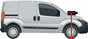
Height of the calibration pattern's origin above the ground, specified as a nonnegative real scalar. The origin is the bottom-right corner of the top-left square of the checkerboard.
The measurement of patternOriginHeight depends on the
orientation of the calibration pattern, as shown in these diagrams.
| Horizontal Orientation | Vertical Orientation |
|---|---|
|
|
|


To specify the pattern orientation, use the
'PatternOrientation' name-value pair. If you set
'PatternOrientation' to 'horizontal'
(default), and the pattern is on the ground, then set
patternOriginHeight to 0.
Data Types: single | double
Name-Value Arguments
Output Arguments
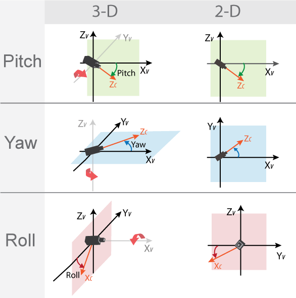
Pitch angle between the horizontal plane of the vehicle and the optical axis of the
camera, returned as a real scalar in degrees. pitch uses the ISO
convention for rotation, with a clockwise positive angle direction when looking in the
positive direction of the vehicle's YV-axis.
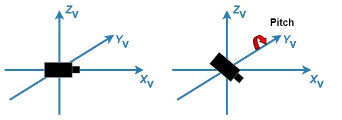
For more details, see Angle Directions.
Yaw angle between the XV-axis of the
vehicle and the optical axis of the camera, returned as a real scalar in degrees.
yaw uses the ISO convention for rotation, with a clockwise
positive angle direction when looking in the positive direction of the vehicle's
ZV-axis.
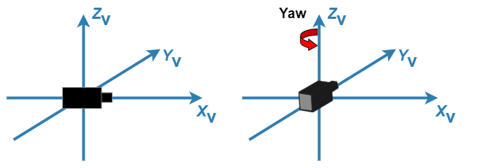
For more details, see Angle Directions.
Roll angle of the camera around its optical axis, returned as a real scalar in
degrees. roll uses the ISO convention for rotation, with a
clockwise positive angle direction when looking in the positive direction of the
vehicle's XV-axis.

For more details, see Angle Directions.
Perpendicular height from the ground to the focal point of the camera, returned as a nonnegative real scalar in world units, such as meters.
More About
In the vehicle coordinate system
(XV,
YV,
ZV) defined by a monoCamera object:
The XV-axis points forward from the vehicle.
The YV-axis points to the left, as viewed when facing forward.
The ZV-axis points up from the ground to maintain the right-handed coordinate system.
By default, the origin of this coordinate system is on the road surface, directly below the camera center (focal point of camera).

To obtain more reliable results from estimateMonoCameraParameters, the calibration
pattern must be placed in precise locations relative to this coordinate system. For more
details, see Calibrate a Monocular Camera.
The monocular camera sensor uses clockwise positive angle directions when looking in the positive direction of the Z-, Y-, and X-axes, respectively.
Version History
Introduced in R2018b
See Also
Apps
Functions
estimateCameraParameters|estimateFisheyeParameters|detectCheckerboardPoints|generateCheckerboardPoints|extrinsics