Main Content

Varying Delay

Varying delay with support for fixed delay and zero delay (direct feedthrough)

Since R2024a

  • Varying Delay block icon

Libraries:
Control System Toolbox / Linear Parameter Varying

Description

The Varying Delay block extends the functionality of the Variable Transport Delay (Simulink) block in the Simulink / Continuous library by providing additional support for specifying fixed and zero delays. This block is helpful when you want to model a mix of zero, fixed, and varying delays, which can occur in LPV models.

Examples

expand all

This example shows how to use the Varying Delay block provided with the Control System Toolbox™ library. This block is useful when you want to model a mix of fixed, varying, and zero delays for individual channels in the signal using just one block.

Open the model provided with this example.

mdl = "varyingDelayModel";
open_system(mdl)

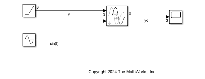
This model contains a ramp source with dimensions 3-by-1. The ramp signals have a slope of 1, 2, and 3 at the corresponding indices. The Sine Wave block generates a signal for the varying delay port.

For this model, specify:

  • A varying delay with a nominal delay of 1 s in the first channel of the ramp signal. The instantaneous value of the varying delay value is provided by the Sine Wave block.

  • A fixed delay of 3 s in the second channel of the ramp signal.

  • A zero delay (feedthrough) for the third channel of the ramp signal.

Configure the block parameters as shown.

Specify the nominal delay parameter as a vector with values 1, 3, and 0 corresponding to the delays in each channel. Use the Fixed delays (indices) parameter to specify fixed delays for channels 2 and 3.

Examine the structure under the block mask. The block automatically configures the delays based on the specified settings. The varying delay input has a Saturation block to ensure that the delay is nonnegative. Therefore, it provides a delay of 0 when sin(t) becomes negative.

Run the model and view the result.

sim(mdl);

As you can see, the first channel has a varying sinusoidal delay, the second channel has a fixed delay of 3 s, and the third channel has zero delay.

close_system(mdl)

Ports

Input

expand all

Input signal specified as a scalar or vector.

This port has direct feedthrough when you specify a signal delay as fixed using the Fixed delays (indices) parameter and specify a value 0 for the Nominal delay parameter.

Data Types: double

Instantaneous time delay input specified as a scalar or vector. This value is used to specify the varying delay. The block treats any negative input values as zero.

Dependencies

To enable this port, specify at least one index as varying, that is, the Fixed delays (indices) parameter must not specify all channels as fixed.

Data Types: double

Output

expand all

Output signal specified as a scalar or vector.

Data Types: double

Parameters

expand all

To edit block parameters interactively, use the Property Inspector. From the Simulink® Toolstrip, on the Simulation tab, in the Prepare gallery, select Property Inspector.

Specify the nominal value of delays in each input channel.

Set the maximum value of the time delay input. This value defines the largest time delay input that this block allows. The block clips any delay that exceeds this value.

Set the minimum value of the time delay input. This value defines the smallest time delay input that this block allows. The block maintains this value for any delay that is less than this value.

Specify the indices of the input signal channels where the delays are fixed. For example, if you have a 4-by-1 input signal and you want to specify fixed delay in the first and fourth channel, use a value [1 4] for this parameter. The block uses the value specified at the corresponding index of the Nominal delay parameter.

When you list all channels as fixed, the block disables the second input port Port_2.

For each input channel, specify the output value until the simulation time first exceeds the time delay for the channel.

Define the initial memory allocation for the number of input points to store. The input points define the history of the input signal up to the current simulation time.

  • If the number of input points exceeds the initial buffer size, the block allocates additional memory.

  • After simulation ends, a message displays if the buffer is not sufficient and more memory must be allocated.

Tips

  • Because allocating memory slows down simulation, choose this value carefully if simulation speed is an issue.

  • For long time delays, this block might use a large amount of memory, particularly for dimensionalized input.

Selecting this check box uses a fixed-size buffer to save input data from previous time steps. When you clear this check box, the block does not use a fixed-size buffer.

The Initial buffer size parameter specifies the buffer size. If the buffer is full, new data replaces data already in the buffer. The software uses linear extrapolation to estimate output values that are not in the buffer.

Note

ERT or GRT code generation uses a fixed-size buffer even if you do not select this check box.

Tips

  • If the input data is linear, selecting this check box can save memory.

  • If the input data is nonlinear, do not select this check box. Doing so might yield inaccurate results.

Set the order of the Pade approximation for linearization routines.

  • The default value is 0, which results in a unity gain with no dynamic states.

  • Setting the order to a positive integer n adds n states to your model, but results in a more accurate linear model of the delay.

Use a vector of positive integers to specify a different order for each input channel.

Extended Capabilities

C/C++ Code Generation
Generate C and C++ code using Simulink® Coder™.

Version History

Introduced in R2024a